Page 5 of 57
Re: Building a Morgan 3-Wheeler Replica
Posted: 24 Jan 2013 04:34
by S15DET
So you'll have a high, narrow hump running through the middle for the driveshaft, that's not so bad. Are you going to use a chain for the final drive to the wheel, or retain the shaft drive from the Goldwing with a u-joint at the rear swing pivot? Maybe two radiators on each side of the driveshaft, hidden just inside the bodywork with side and bottom airflow exit paths, and a flap/diverter to allow them to serve as a whole "cabin" heater?
Re: Building a Morgan 3-Wheeler Replica
Posted: 24 Jan 2013 06:51
by okayfine
Shaft-drive all the way. Probably the biggest reason I went with the Goldwing as a donor.
I'd thought about trying build a way for the radiators to also be heaters. I'm not there yet. I'd like to use the GW radiator for cost purposes, but we'll see. I also need to find a grill/nose cone to give me a sense of how much space I have to work with. A LOT of chicken or egg stuff now.
Good Vibrations
Posted: 26 Jan 2013 18:27
by okayfine
As mentioned, I was waiting for a set of poly sway bar bushings to arrive so I could finalize the mounting of the engine. They came last night and I got to work this afternoon. The Goldwing engine is mounted to the Goldwing in a few spots. I'm going to use two of them at the moment, the bottom-front and bottom-rear mountings.
The bottom-rear was the easier of the two to design. I cut the stock brackets off the bike chassis and cut some flat plate to act as the landing pads. I also drilled the engine mounting rails to take a 8x1.25 nut, giving me a way to secure the mount through the bushing. The final will definitely get LocTite. Everything on this thing is going to get LocTite.
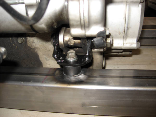
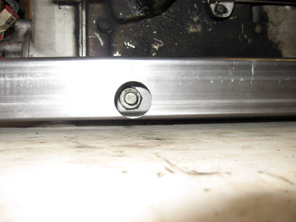
The bottom-front utilized a long through-bolt, nutted on each side. I drilled through the 2x2 engine mount rails and used a hole saw on the outer sides of the rails to open up the holes so I could get a 19mm socket inside the rails to tighten the bolts.
Bushings between the rails and the case:
With the engine successfully mounted to the rails, I could then attach the rails to the chassis.
Bracing the Engine Mount Rails
Posted: 26 Jan 2013 18:38
by okayfine
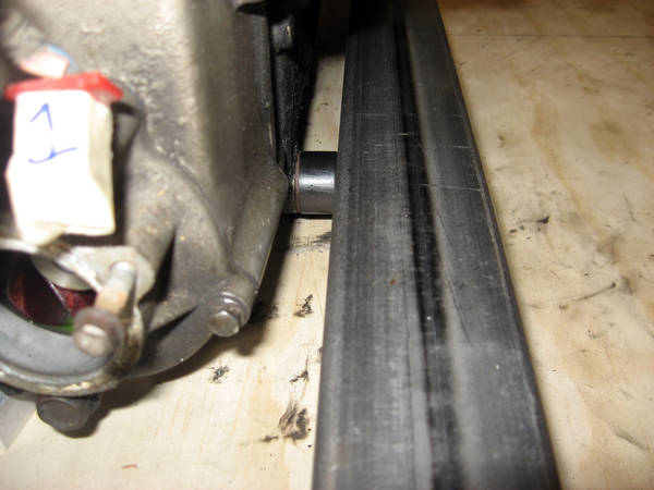
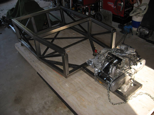
Couple of things happened, leading me to my current status. I mocked up the engine placement and the rear end placement, then placed a length of 1x1 tube between the engine output and the rear input. The output on the engine is offset, it doesn't come out in the center. I knew about this, but didn't know how much of an impact it would be in the Morgan until I was able to mock them up. The result as it was was that the driveshaft was going to be high and tight for the right-seat passenger.
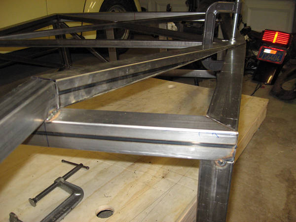
To somewhat lessen the impact of this, I decided to raise the tub up by 2" and run the engine mounting rails underneath the front of the tub. Somewhat inelegant, I admit, but I don't have a lot of choice if I want to carry a passenger. In addition to the position of the DS through the cockpit, I also have to built a trans tunnel around it, further impacting room.
In any case, that brings us to where we are with the chassis, with the engine mounting rails welded to the front of the tub.
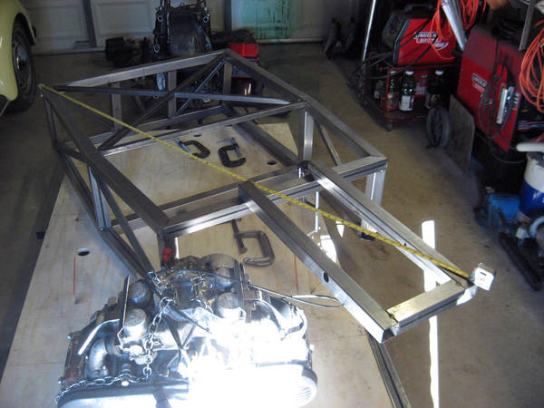
Even with upper braces eventually connected to the rails (and supporting the upper a-arms), that still seems pretty flexible. To counter this, I cut up some 2x2 box tube:
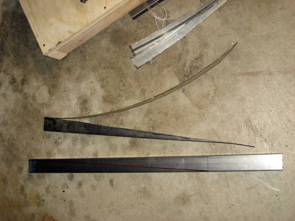
To make braces that run from the engine mounting rails and front of the tub to the "b-pillars" of the tub:
This should provide some improvement in stiffness for the whole chassis. I'll have more to do for that, but I have to finish welding up the braces and weld them into the chassis. I'd also like to weld all the bottom welds of the chassis so I don't have to flip it over again until I paint it.
Hey Big Spender
Posted: 27 Jan 2013 18:11
by okayfine
First big outlay for the project, aside from the OG Goldwing. Wilwood front disc brake setup for Mustang II spindles. Half price on eBay:

- $T2eC16FHJGoE9nuQeWveBQ-1gBq2hQ~~60_57.JPG (209.95 KiB) Viewed 6312 times
$4058.17 - $321.10 = $3737.07.
However, I also sold the dogleg trans, so... $3987.07.
I hadn't decided on which way to go with the front suspension/steering/spindles, etc. Lots of ways to go. The MII stuff is pretty ubiquitous in hot-rod circles, so readily available and not too expensive. MII is normally front-steer, but Wilwood makes rear-steer spindles, and then I just need to find a rear-steer rack that will take Ford tie-rods.
Re: Building a Morgan 3-Wheeler Replica
Posted: 27 Jan 2013 19:40
by finn
Great progress. I still laugh to myself picturing you drive this thing. (Head over the windshield) are you going to "c" knotch the those mount holes?
Re: Building a Morgan 3-Wheeler Replica
Posted: 27 Jan 2013 20:57
by Byron510
Just a thought about your horizontal mount shown above.
Usually you would put some type of doubler plate behind a mount like this to spread out the load. Another option is to weld a tube fully through the box sections to spread the torque over a larger area. This also helps keep that section of the tube rigid as well.
Just some thoughts for ya to possibly consider.
Byron
Re: Building a Morgan 3-Wheeler Replica
Posted: 28 Jan 2013 07:00
by okayfine
Thanks for the insight on strengthening the mount holes. Definitely chime in in the future if you see things that might need improvement.
I'll have a sit and think to see what I can do with what I've done.
Bottom Welding
Posted: 28 Jan 2013 16:22
by okayfine
I added doubler plates on the engine mount rails to reinforce the side mounting. Then I went about welding all bottom-facing seams in the tub. I wanted to do this so I could then flip the tub right-side up and put it back into position with the engine mounted, but I also had to do the welding before I could weld in the angled braces from above. This is mainly because where the braces attach to the sides of the tube, they will overlap the "b-pillar" joints. So all bottom-facing welds got some love, then I sanded all those welds flat so the eventual flat-bottom aluminum sheet will sit flat against the 2x2 tubes.
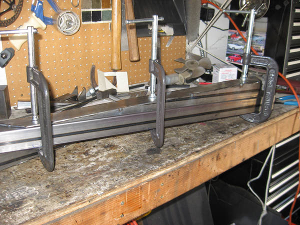
Then I could finish the angled braces for the engine mount rails. After cutting to shape, I c-clamped each one to another 2x2 tube and welded the seams:
Then the braces got welded to the chassis:
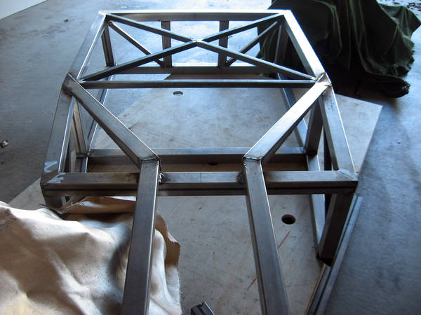
After that and some clean-up, I flipped the chassis back over, slid it under the engine, and bolted the engine up for reals:
Re: Building a Morgan 3-Wheeler Replica
Posted: 29 Jan 2013 15:12
by okayfine
$3987.07 minus:
$46.47 for two Mustang II lower balljoints
$362.89 for two Wilwood Mustang II 2" drop Pro Spindles
$29.90 for eight Chevelle LCA bushings
$3547.81 remaining.
Re: Building a Morgan 3-Wheeler Replica
Posted: 30 Jan 2013 17:43
by McShagger510
Re: Building a Morgan 3-Wheeler Replica
Posted: 31 Jan 2013 06:57
by okayfine
I thought Top Gear killed off the black STIG?
I need to find a couple of those aero screens.
Re: Building a Morgan 3-Wheeler Replica
Posted: 31 Jan 2013 07:38
by S15DET
Always listed as Brookslands Screens in all the brit-car catalogs, should be available from many sources.
Re: Building a Morgan 3-Wheeler Replica
Posted: 31 Jan 2013 07:43
by two_68_510s
Re: Building a Morgan 3-Wheeler Replica
Posted: 31 Jan 2013 08:36
by okayfine
Brilliant!