Very interesting reading on the new turbo tech, a lot has come & gone since I hobbled Blue together with the Z24.
I imagine the meth will be computer controlled, anyway will be watching your progress Jordan.
Jordan's '72 2 door KA project

Re: Jordan's '72 2 door KA project
I knew that I was going to be doing some modifying as well, so I asked Jeff to send me a set of motor mounts tacked together but not finished, and managed to get the motor 0.8mm (lower) from the original height. Had to use a small shim in the process. I can always ad to the shim later if need be, but am hoping that I am close enough. I have had cars in the past with driveline vibration issues, and nothing will drive you crazier than trying to make those go away completely. It gets in your head and you feel it even when it isn't there. Matt's car has no vibration issues, which is why I have focused on keeping things in their exact location.
As for the rack setup, no I haven't had a chance to try it out. I ended up going with the red rack isolators, and they seem stiff enough and fit into the bracket snuggly, but am not sure if the black ones are a better option. The crossmember is in, and next step is to commit to the exact position of the LCA on the pivot bolt by installing the spacer where the LCA is perpendicular to the crossmember. My stock LCAs have custom spherical bearings installed, so my intention is to continue using them. My wheel track is just under a half inch wider per side now, and to maintain the same camber angle, the strut has to be pulled out by approximately the same amount. I should know by tomorrow if I will have tire fitment issues when the prior camber angle is restored. It looks like it is going to be close.
It has been a slick installation so far. The next step is to deal with the steering column. I am really looking forward to trying it out in the spring, and anticipate that it is going to do wonders for steering response and feedback. I went with the same ratio as you did, which will be quicker than the stock box but not aggressively so. It is nice to know that quick ratio racks are just a click away if a tighter ratio is desired.
Jason

Re: Jordan's '72 2 door KA project
Hey Jason,JasonLee wrote: ↑19 Nov 2018 22:12 I knew that I was going to be doing some modifying as well, so I asked Jeff to send me a set of motor mounts tacked together but not finished, and managed to get the motor 0.8mm (lower) from the original height. Had to use a small shim in the process. I can always ad to the shim later if need be, but am hoping that I am close enough. I have had cars in the past with driveline vibration issues, and nothing will drive you crazier than trying to make those go away completely. It gets in your head and you feel it even when it isn't there. Matt's car has no vibration issues, which is why I have focused on keeping things in their exact location.
As for the rack setup, no I haven't had a chance to try it out. I ended up going with the red rack isolators, and they seem stiff enough and fit into the bracket snuggly, but am not sure if the black ones are a better option. The crossmember is in, and next step is to commit to the exact position of the LCA on the pivot bolt by installing the spacer where the LCA is perpendicular to the crossmember. My stock LCAs have custom spherical bearings installed, so my intention is to continue using them. My wheel track is just under a half inch wider per side now, and to maintain the same camber angle, the strut has to be pulled out by approximately the same amount. I should know by tomorrow if I will have tire fitment issues when the prior camber angle is restored. It looks like it is going to be close.
It has been a slick installation so far. The next step is to deal with the steering column. I am really looking forward to trying it out in the spring, and anticipate that it is going to do wonders for steering response and feedback. I went with the same ratio as you did, which will be quicker than the stock box but not aggressively so. It is nice to know that quick ratio racks are just a click away if a tighter ratio is desired.
Thanks for the time you spent putting these posts together. I think I ended up with the engine in the same position. More updates soon.
'72 2 door KA project | S14 Silvia RB25DET | S14 RB26DETT (sold) | '90 Audi 90Q20V (sold)
Re: Jordan's '72 2 door KA project
Remember when..?
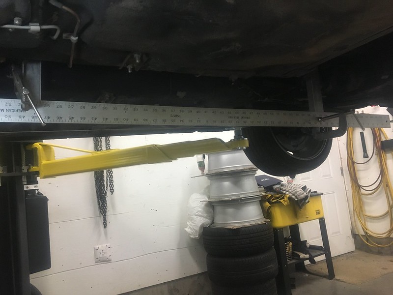
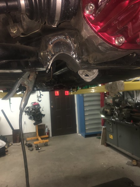
I want to get away from having the diff shimmed down at the back because this causes the CVs to have poor operating angles. I test fit the JBC mounts and removed the all the shims from the diff moustache bar and measured the driveline angle. The vertical misalignment was 3.5* at this point. Since the diff was back in its proper place, this required adjustments to be made at the engine and transmission mounts to correct this. I could only lower the engine ~ 1.125" before it got too close to the crossmember and rack so the remaining 0.6" had to come from raising the transmission. To do that, I had to cut apart the transmission tunnel cover I build back in the day. All in all, it was pretty depressing redoing bad work but the results should be much better and the engine has a lot of clearance out front for fans, cooling, interfoolin' etc.
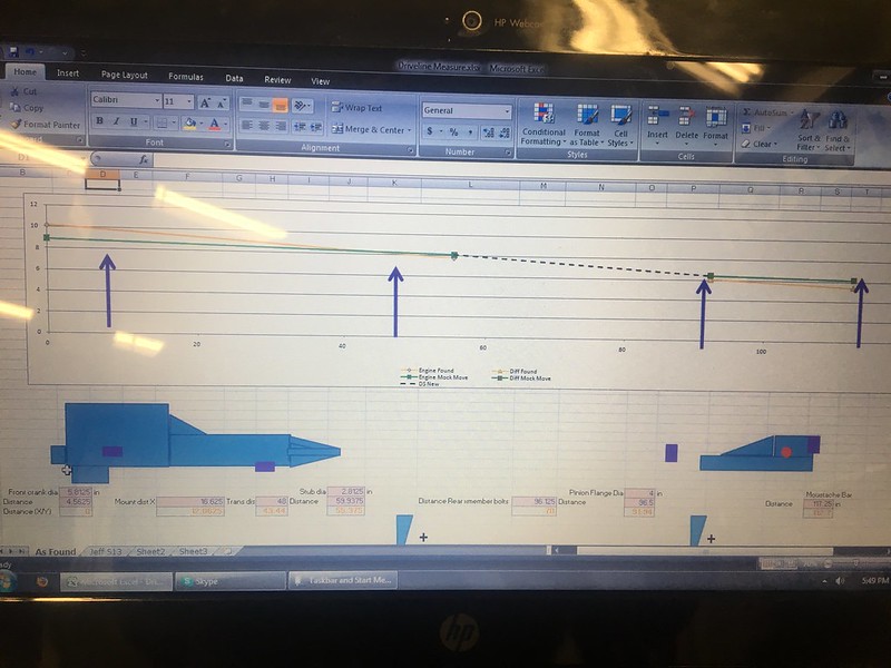
I went full nerd mode in excel and graph out how it all looks so you can calculate shims etc. without just guessing.
 IMG_7095 by JordanTr, on Flickr
 IMG_7094 by JordanTr, on Flickr
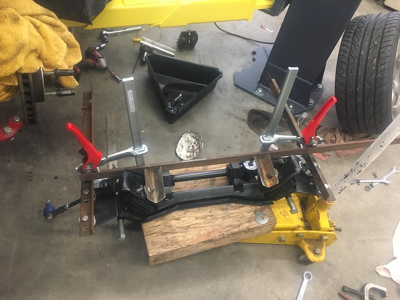
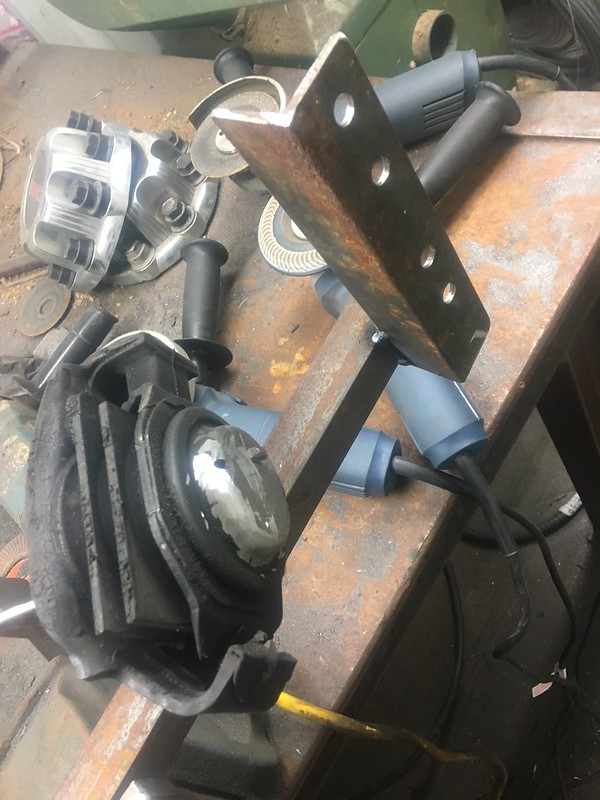
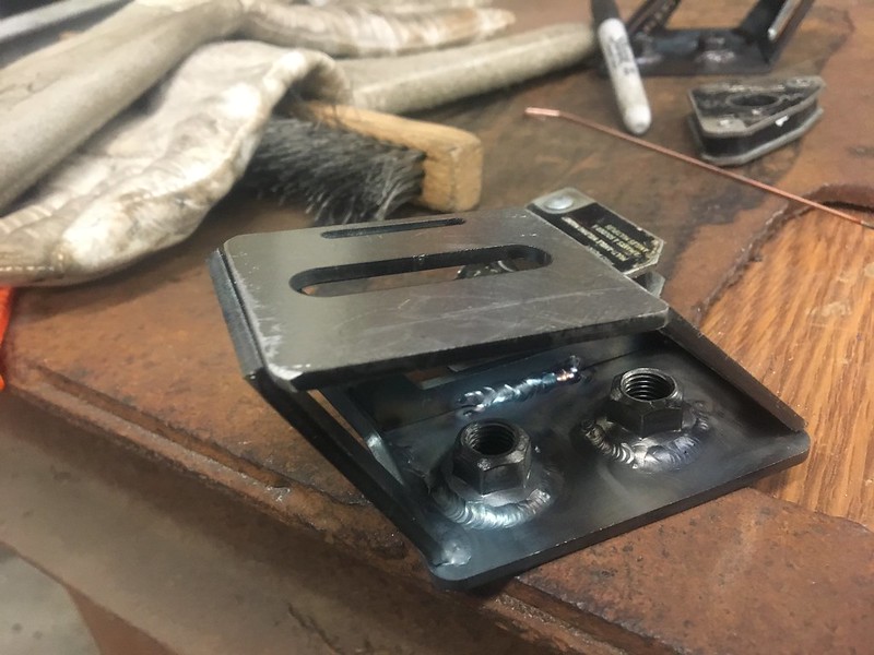
To perform the moves at the engine, I build a jig to allow a 1.25" rearward movement and a 1.125" drop of the engine using the lower engine mounts. I didn't want to modify the upper engine mounts since I am getting cramped on room above them when the S13 rubber isolators are used. I got the tapped plate idea from Jason's posts above and figured that if I could make the S13 mounts bolt in like the stock 510 mounts then I could eliminate all the vertical space required to use the studs on the S13 mounts. Here are some pictures of the journey!
 IMG_7102 by JordanTr, on Flickr
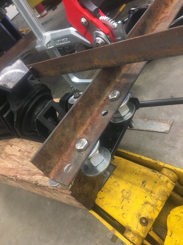
1.125" spacers and second set of holes @ 1.25" to remount the jig with the new engine "position".
 IMG_7103 by JordanTr, on Flickr
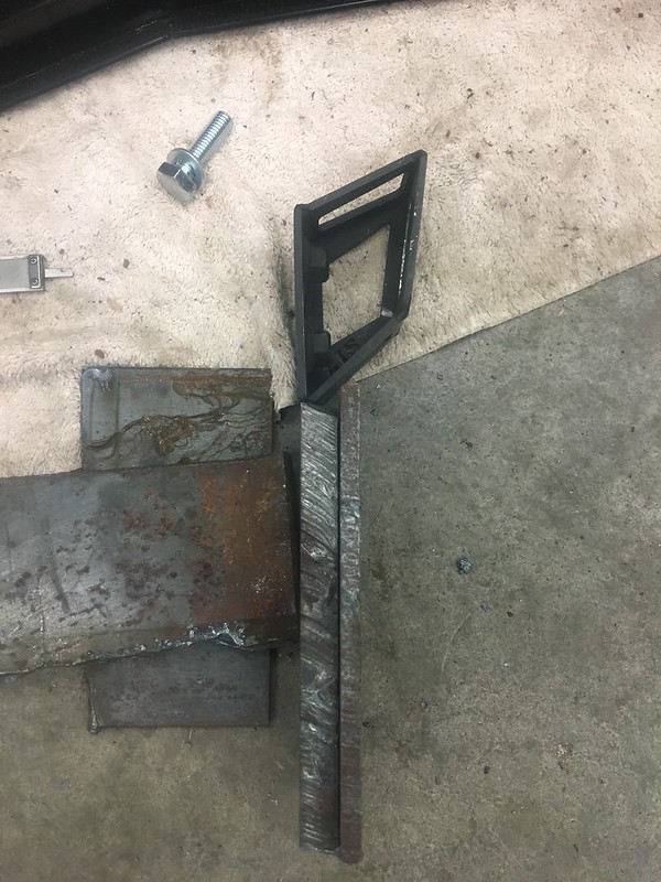
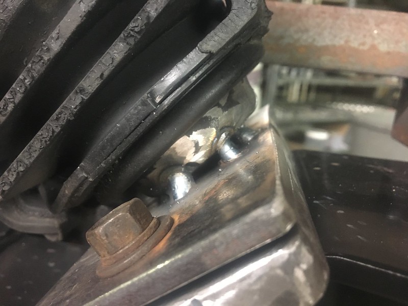
Goodbye stud!!
 IMG_7104 by JordanTr, on Flickr
CAD template.
 IMG_7106 by JordanTr, on Flickr
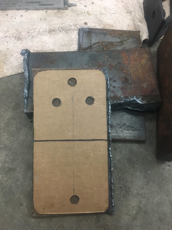
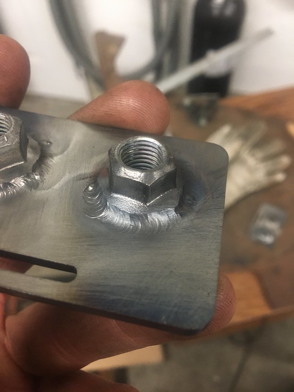
The lower plate is 1/2" and is tapped with 5 holes. 3 securing it to the xmember and 2 to secure the engine mount down.
My phone died while burning the midnight oil so I missed a few pictures.
 IMG_7109 by JordanTr, on Flickr
 IMG_7110 by JordanTr, on Flickr
 IMG_7115 by JordanTr, on Flickr
Just tacked for now.
 IMG_7117 by JordanTr, on Flickr
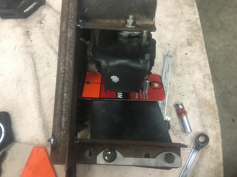
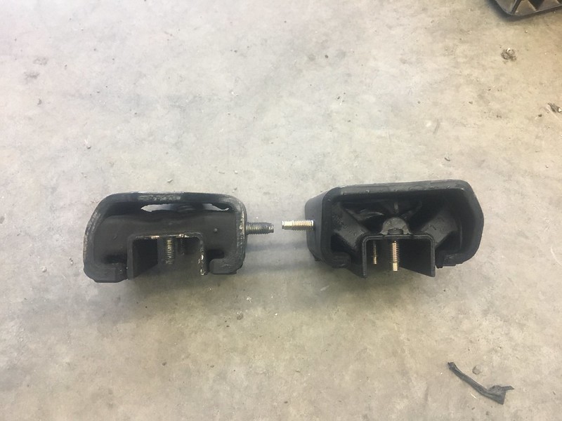
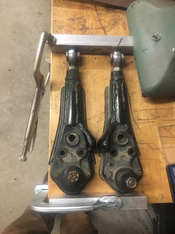
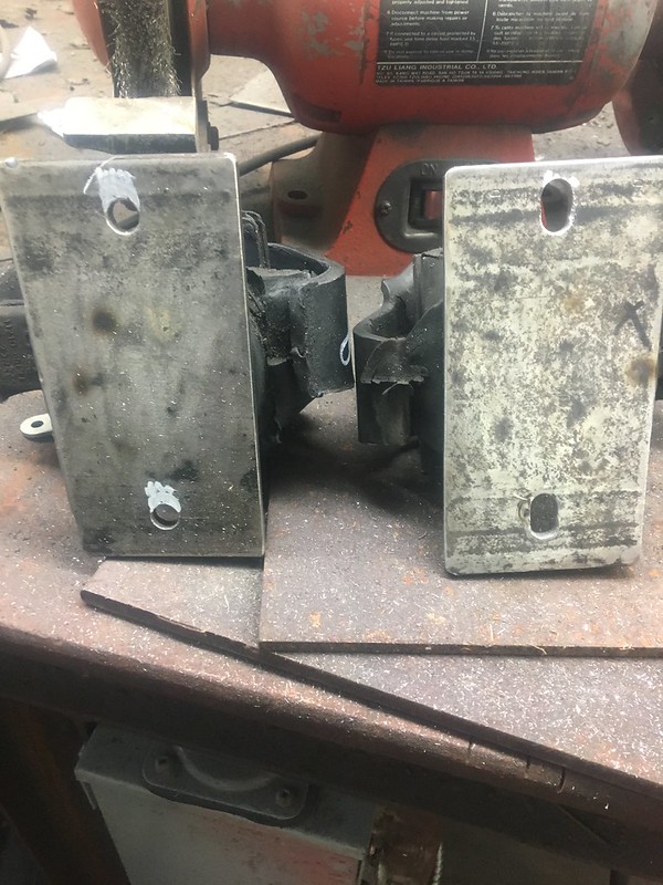
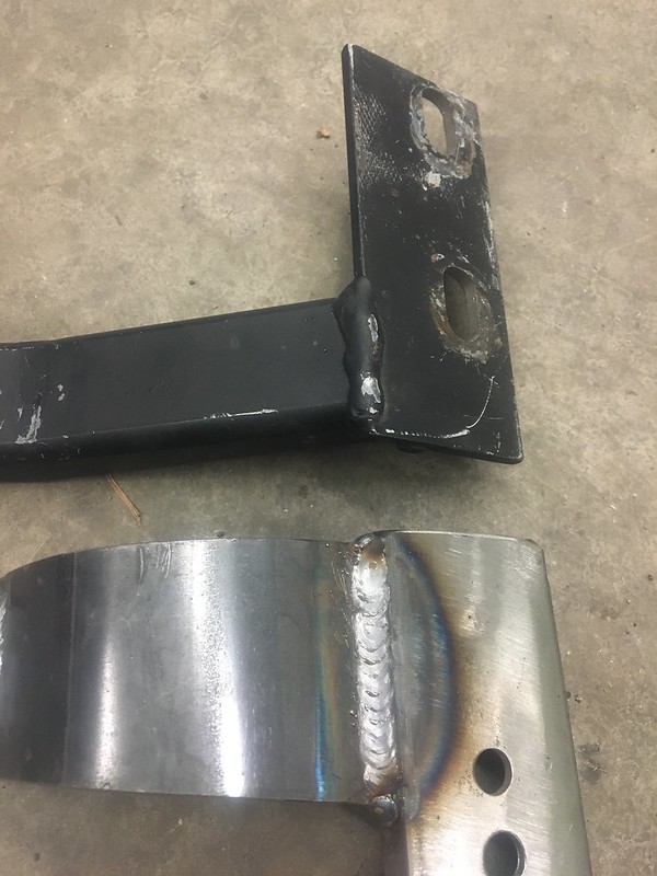
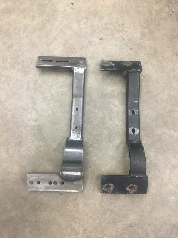
Once installed and re-measured, it verified that there was indeed still 0.6" to go up at the trans mount. This also verified my SOHCAHTOA. I will be switching from the OEM Z32 trans mount to an S13/S14 Nismo one to reduce transmission movement. I went this way on the S14s and it is just right I think. Picture below shows the 2 different mounts side by side.
 IMG_7100 by JordanTr, on Flickr
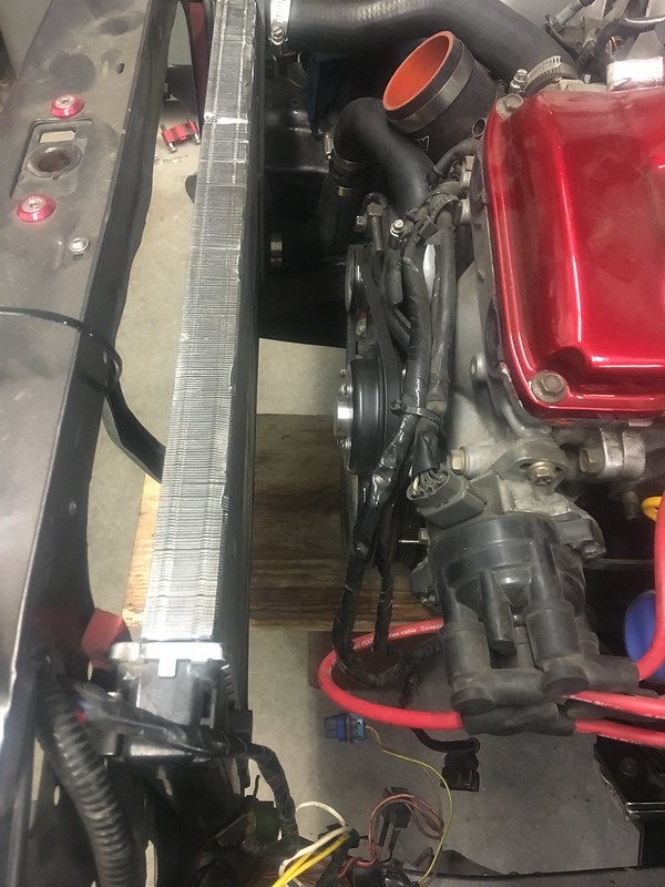
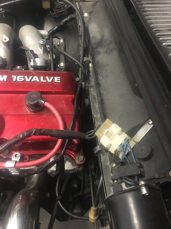
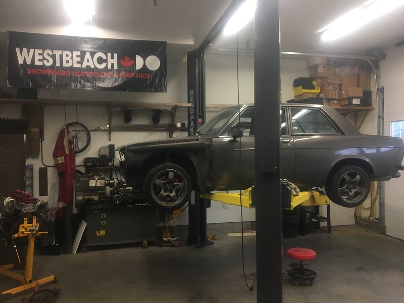
The extra room is apparent up front.
 IMG_7120 by JordanTr, on Flickr
 IMG_7121 by JordanTr, on Flickr
First on the task list to do once back in the shop is to fab a new transmission mount to accommodate the new engine position and to raise the transmission tail up.
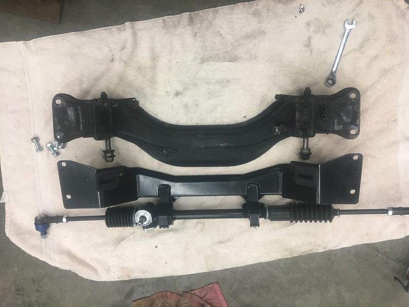
Rack Install
 IMG_7089 by JordanTr, on Flickr
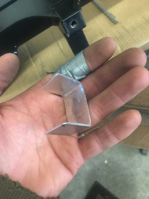
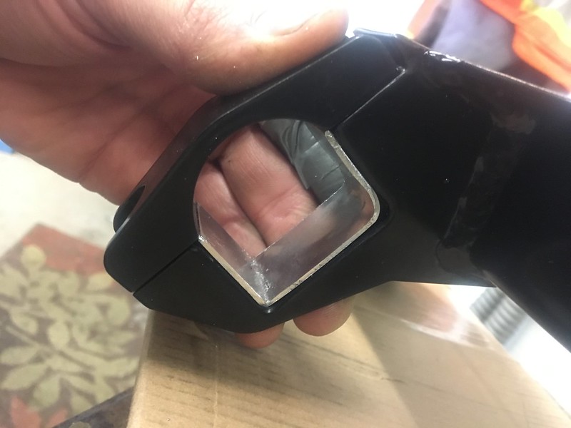
With the known issues with steering rack bushings, I was able to build a U shaped shim from 0.065" aluminum and press it into the rack on the non-drive side. This nicely snugged that mount up. The drivers mount was super tight as is.
 IMG_7024 by JordanTr, on Flickr
 IMG_7025 by JordanTr, on Flickr
I bought the DIY mounts and TIG welded them. Didn't end up using them but it was good welding practice!
 IMG_7045 by JordanTr, on Flickr
 IMG_7053 by JordanTr, on Flickr
I adjusted my lower control arms to account for the extra 1/2" track width. After removing the 1/8" spacers, I equalized the LCA length and shortened them a combined total of 1/4" to offset the extra track width. Notice my special addition feeler gauges. They are round and only come in 1/64" increments!
 IMG_7092 by JordanTr, on Flickr
Got this to make life a little easier around the car!!
 IMG_7077 by JordanTr, on Flickr
Machined up a little adaptor to get my VDO oil pressure gauge working.
 IMG_7064 by JordanTr, on Flickr
I was able to pick up an EVO 7 intercooler and it is approximately the right size. Being tube and fin, the end tanks have large flanges which may be tough to fit. We will see.
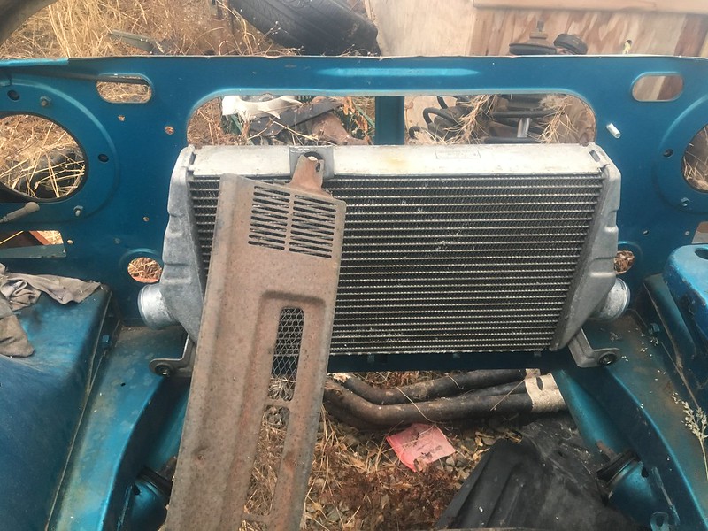 IMG_6930 by JordanTr, on Flickr
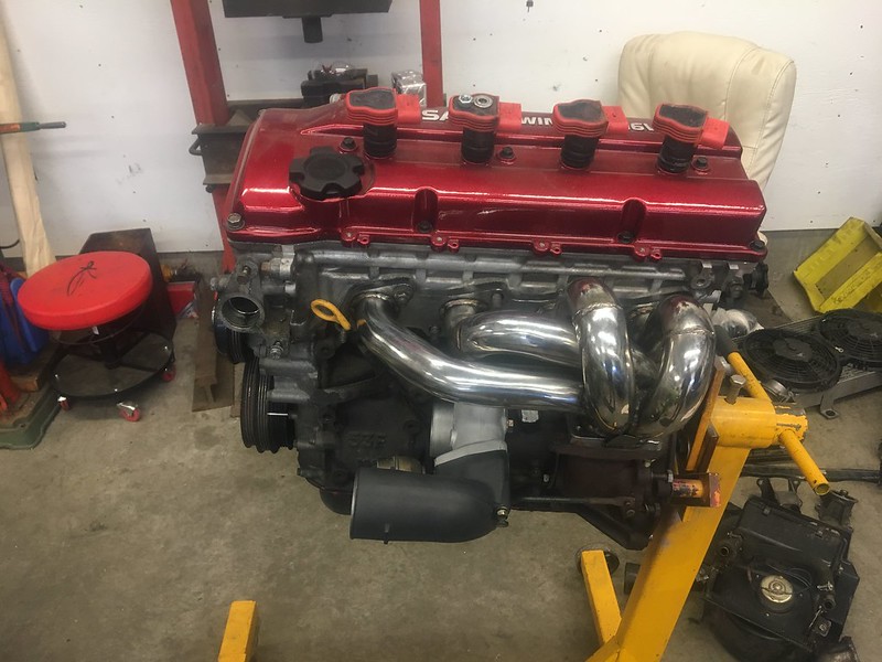
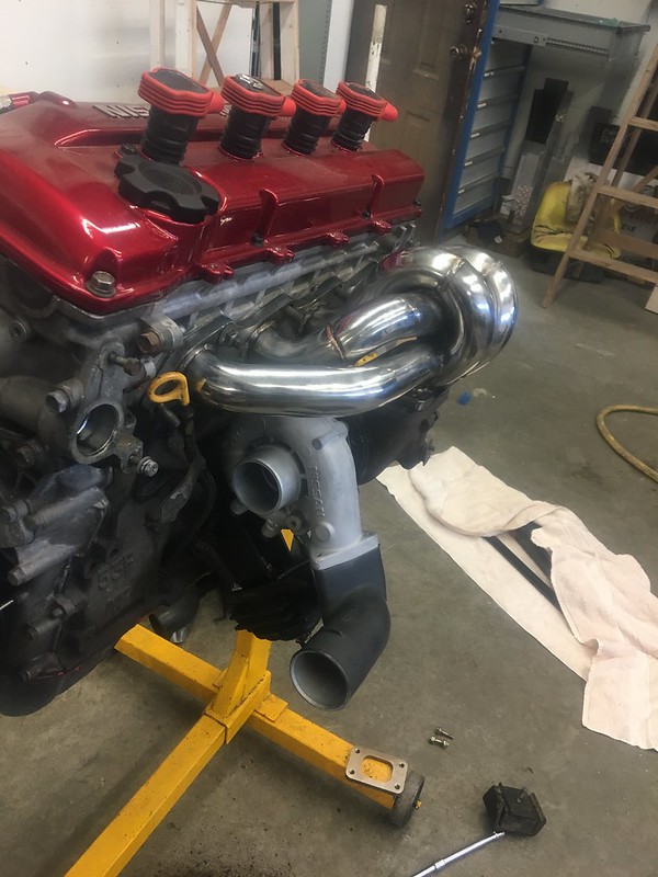
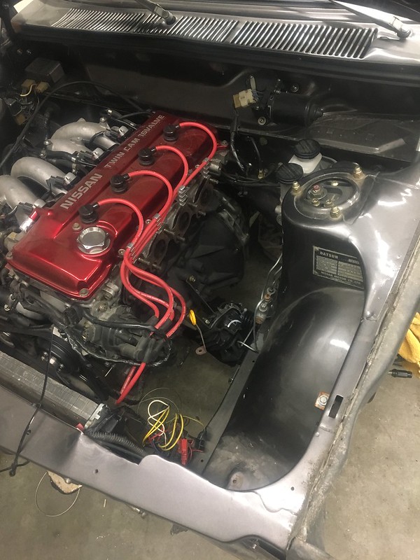
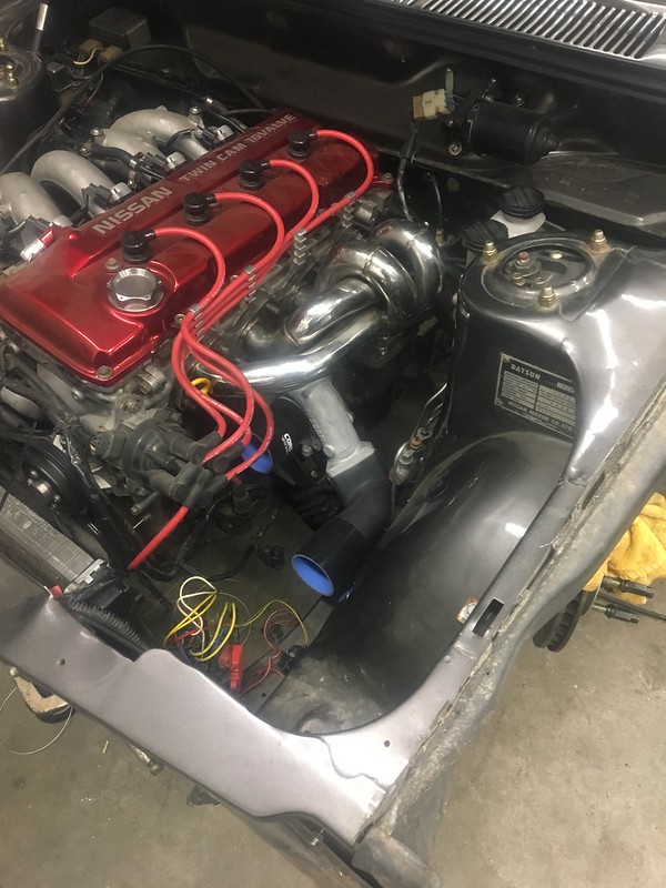
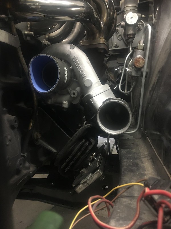
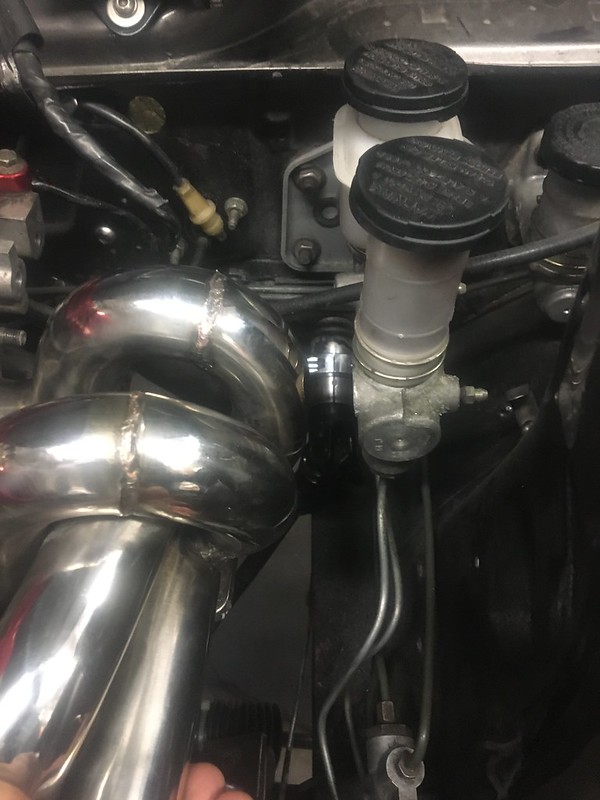
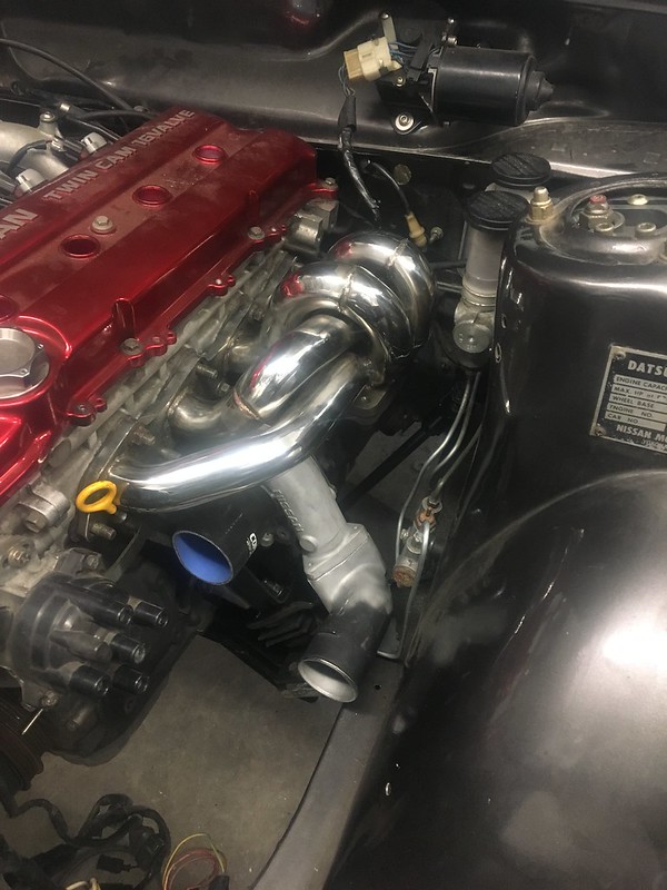
Got the turbocharger mocked up a bit. The ebay manifold is poor quality like expected but the fitment is actually pretty reasonable. Obviously still need to swap a T3 flange on and maybe do some more work to help it fit. With the engine in its new low and back position there is maybe 2mm clearance to the brake master. Audi red top coils have yet to be modified to sit properly in the holes. I may try to step drill some extra space so the factory Audi grommet can be utilized more.
 IMG_7018 by JordanTr, on Flickr
 IMG_7019 by JordanTr, on Flickr
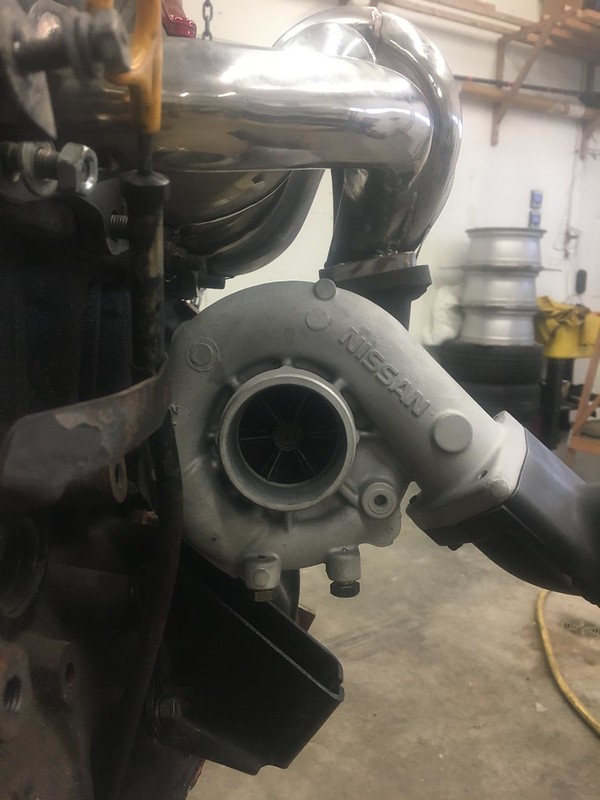
The T2 flange on the manifold looks like it was chromed?? Maybe $80 doesn't get you a stainless manifold lol.
 IMG_7059 by JordanTr, on Flickr
 IMG_7096 by JordanTr, on Flickr
 IMG_7097 by JordanTr, on Flickr
 IMG_7059.JPG by JordanTr, on Flickr
Got a sweet license plate given to me. Unfortunately I can't use it but it'll look cool on the wall!
 IMG_7101 by JordanTr, on Flickr
I've been trying to plan out some of the plumbing for the turbo as well. With the rack, there is ample room for a divorced wastegate downpipe so that will make for a fun fab project!
It appears I can use the water drain in the block to supply water to the turbo. I need a 1/4" BSP male to M14 female so I can run a banjo fitting from there to the turbo just like the RBs. I'm trying to run the lines as similar to a factory RB as I can. The only really non OE looking line will be the oil feed from the filter housing on the other side of the block to the turbo.
The obligatory short term list:
Fab new trans mount, hack tunnel further
Verify driveline alignment.
Rebuild tunnel
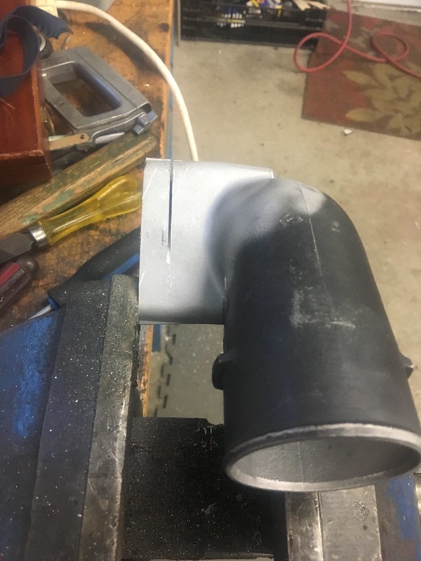
Shorten RB25 compressor elbow to improve clearance to engine mount/inner fender
Modify turbo manifold to improve brake master clearance (section 1/4"-3/8" out of the runners at the flange)
Finalize turbo placement
Weld out T3 flange
Build downpipe
+ 1 million other things.
Stay tuned!
I spent a lot of time this past week working to rectify the above situation. I needed to remount the engine because of the rack and pinion and I also needed to move the engine further back to gain some clearance up front.JordanTr wrote: ↑08 Apr 2014 22:52 Spent all afternoon and evening under the car today... Pulled the whole rear end so I could clearance the crossmember to mess around with the diff shims. Initially, I had foolishly assumed that all would be well with the CV driveshaft so I stuffed the shims up top. Poor choice, and I payed for it today. Now it's all back together. After getting the diff shims below the diff and the car lifted up and sprung, pops and I popped a few different shims above the moustache bar to try to get the pinion and output shaft parallel. After adding 3/4" of spacers above the moustache bar, we were able to get the misalignment to an acceptable 0.7*. Tomorrow will be test drive time with the driveshaft alignment.
I want to get away from having the diff shimmed down at the back because this causes the CVs to have poor operating angles. I test fit the JBC mounts and removed the all the shims from the diff moustache bar and measured the driveline angle. The vertical misalignment was 3.5* at this point. Since the diff was back in its proper place, this required adjustments to be made at the engine and transmission mounts to correct this. I could only lower the engine ~ 1.125" before it got too close to the crossmember and rack so the remaining 0.6" had to come from raising the transmission. To do that, I had to cut apart the transmission tunnel cover I build back in the day. All in all, it was pretty depressing redoing bad work but the results should be much better and the engine has a lot of clearance out front for fans, cooling, interfoolin' etc.
I went full nerd mode in excel and graph out how it all looks so you can calculate shims etc. without just guessing.
IMG_7095 by JordanTr, on FlickrIMG_7094 by JordanTr, on FlickrTo perform the moves at the engine, I build a jig to allow a 1.25" rearward movement and a 1.125" drop of the engine using the lower engine mounts. I didn't want to modify the upper engine mounts since I am getting cramped on room above them when the S13 rubber isolators are used. I got the tapped plate idea from Jason's posts above and figured that if I could make the S13 mounts bolt in like the stock 510 mounts then I could eliminate all the vertical space required to use the studs on the S13 mounts. Here are some pictures of the journey!
IMG_7102 by JordanTr, on Flickr1.125" spacers and second set of holes @ 1.25" to remount the jig with the new engine "position".
IMG_7103 by JordanTr, on FlickrGoodbye stud!!
IMG_7104 by JordanTr, on FlickrCAD template.
IMG_7106 by JordanTr, on FlickrThe lower plate is 1/2" and is tapped with 5 holes. 3 securing it to the xmember and 2 to secure the engine mount down.
My phone died while burning the midnight oil so I missed a few pictures.
IMG_7109 by JordanTr, on FlickrIMG_7110 by JordanTr, on FlickrIMG_7115 by JordanTr, on FlickrJust tacked for now.
IMG_7117 by JordanTr, on FlickrOnce installed and re-measured, it verified that there was indeed still 0.6" to go up at the trans mount. This also verified my SOHCAHTOA. I will be switching from the OEM Z32 trans mount to an S13/S14 Nismo one to reduce transmission movement. I went this way on the S14s and it is just right I think. Picture below shows the 2 different mounts side by side.
IMG_7100 by JordanTr, on FlickrThe extra room is apparent up front.
IMG_7120 by JordanTr, on FlickrIMG_7121 by JordanTr, on FlickrFirst on the task list to do once back in the shop is to fab a new transmission mount to accommodate the new engine position and to raise the transmission tail up.
Rack Install
IMG_7089 by JordanTr, on FlickrWith the known issues with steering rack bushings, I was able to build a U shaped shim from 0.065" aluminum and press it into the rack on the non-drive side. This nicely snugged that mount up. The drivers mount was super tight as is.
IMG_7024 by JordanTr, on FlickrIMG_7025 by JordanTr, on FlickrI bought the DIY mounts and TIG welded them. Didn't end up using them but it was good welding practice!
IMG_7045 by JordanTr, on FlickrIMG_7053 by JordanTr, on FlickrI adjusted my lower control arms to account for the extra 1/2" track width. After removing the 1/8" spacers, I equalized the LCA length and shortened them a combined total of 1/4" to offset the extra track width. Notice my special addition feeler gauges. They are round and only come in 1/64" increments!
IMG_7092 by JordanTr, on FlickrGot this to make life a little easier around the car!!
IMG_7077 by JordanTr, on FlickrMachined up a little adaptor to get my VDO oil pressure gauge working.
IMG_7064 by JordanTr, on FlickrI was able to pick up an EVO 7 intercooler and it is approximately the right size. Being tube and fin, the end tanks have large flanges which may be tough to fit. We will see.
IMG_6930 by JordanTr, on FlickrGot the turbocharger mocked up a bit. The ebay manifold is poor quality like expected but the fitment is actually pretty reasonable. Obviously still need to swap a T3 flange on and maybe do some more work to help it fit. With the engine in its new low and back position there is maybe 2mm clearance to the brake master. Audi red top coils have yet to be modified to sit properly in the holes. I may try to step drill some extra space so the factory Audi grommet can be utilized more.
IMG_7018 by JordanTr, on FlickrIMG_7019 by JordanTr, on FlickrThe T2 flange on the manifold looks like it was chromed?? Maybe $80 doesn't get you a stainless manifold lol.
IMG_7059 by JordanTr, on FlickrIMG_7096 by JordanTr, on FlickrIMG_7097 by JordanTr, on FlickrIMG_7059.JPG by JordanTr, on FlickrGot a sweet license plate given to me. Unfortunately I can't use it but it'll look cool on the wall!
IMG_7101 by JordanTr, on FlickrI've been trying to plan out some of the plumbing for the turbo as well. With the rack, there is ample room for a divorced wastegate downpipe so that will make for a fun fab project!
It appears I can use the water drain in the block to supply water to the turbo. I need a 1/4" BSP male to M14 female so I can run a banjo fitting from there to the turbo just like the RBs. I'm trying to run the lines as similar to a factory RB as I can. The only really non OE looking line will be the oil feed from the filter housing on the other side of the block to the turbo.
The obligatory short term list:
Fab new trans mount, hack tunnel further
Verify driveline alignment.
Rebuild tunnel
Shorten RB25 compressor elbow to improve clearance to engine mount/inner fender
Modify turbo manifold to improve brake master clearance (section 1/4"-3/8" out of the runners at the flange)
Finalize turbo placement
Weld out T3 flange
Build downpipe
+ 1 million other things.
Stay tuned!
'72 2 door KA project | S14 Silvia RB25DET | S14 RB26DETT (sold) | '90 Audi 90Q20V (sold)
Re: Jordan's '72 2 door KA project
Big update, nice.
Re: Jordan's '72 2 door KA project
Nice work!

Re: Jordan's '72 2 door KA project
finally some boost!!!
"People don't like it when shit doesn't match their rule of thumb." Sam
-
vetteguy22
- Posts: 69
- Joined: 05 Dec 2016 22:19
- Location: Prescott Valley AZ
Re: Jordan's '72 2 door KA project
Hi Jordan,
Incredible work.
I have a question about the mod you did to your LCA.
I understand you used 1 1/4” 0.125 DOM tubing but is the heim joint threaded end just inserted in the tubing or did you tap the inside so the heim is secured?
Also, did you make adjustable TC arms or did you purchase some?
If you made them, how did you go about it and what materials did you use?
Keep up the great work and wonderful build thread.
Rob
Re: Jordan's '72 2 door KA project
Hey Rob,vetteguy22 wrote: ↑02 Jan 2019 21:57 Hi Jordan,
Incredible work.
I have a question about the mod you did to your LCA.
I understand you used 1 1/4” 0.125 DOM tubing but is the heim joint threaded end just inserted in the tubing or did you tap the inside so the heim is secured?
Also, did you make adjustable TC arms or did you purchase some?
If you made them, how did you go about it and what materials did you use?
Keep up the great work and wonderful build thread.
Rob
Thanks! It's hard to believe the thread has gone this far.
I bought threaded tube adapters from Ballistic Fab. https://www.ballisticfabrication.com/co ... 5793760775 . My setup isn't easily adjustable in the car since it doesn't have a turnbuckle setup but I just wanted to adjust the LCAs for wheel fitment and it does that well.
Here's the original post with the arm build viewtopic.php?f=3&t=12637&start=255#p216655
I bought the T3 TC rods. They work but the angle on the bolt holes for the LCA is wrong so you have to drill the holes out to fit it. This gets worse once things move around with the JBC crossmember so now the holes are drilled out and slotted. It works for now so I'm focused elsewhere, Maybe one day I'll build something that has better sway bar clearance, maintains the stock pivot point in the TC box, and bolts on properly!
'72 2 door KA project | S14 Silvia RB25DET | S14 RB26DETT (sold) | '90 Audi 90Q20V (sold)
Re: Jordan's '72 2 door KA project
I spent another few days in the shop so we are due for another update.
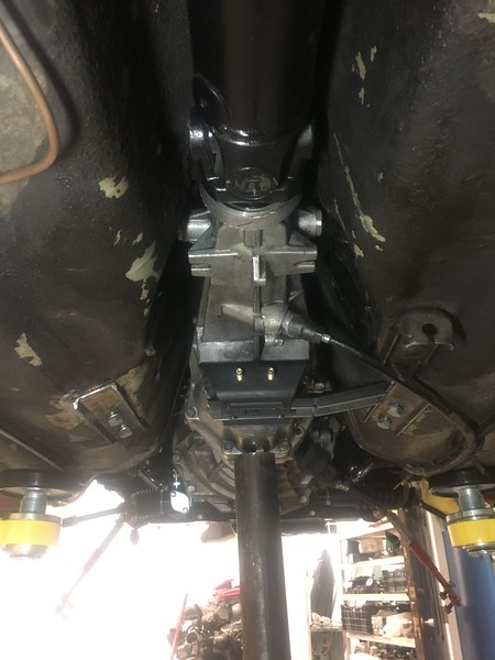
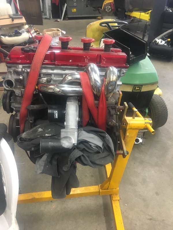
I was able to move the engine rearward another 5/16" and I did that by slotting the new engine mount lower plates. It also makes it a little easier to install which is nice. With the engine in its final home, I rebuilt the transmission crossmember. The design is pretty similar to what I had back in 2009 (!!!) and miraculously I was able to find the other half of the square tube I split back in the day. I used a reshaped piece of 6" sched 40 pipe for exhaust clearance on the drivers side.
 510 NY 2019 by JordanTr, on Flickr
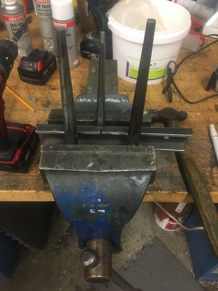
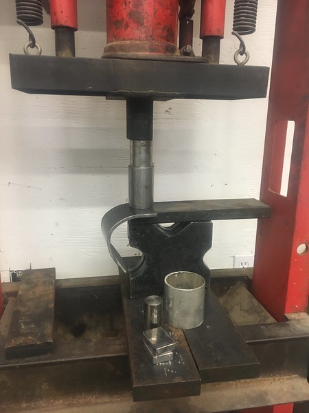
Homemade press
 510 NY 2019 by JordanTr, on Flickr
 510 NY 2019 by JordanTr, on Flickr
 510 NY 2019 by JordanTr, on Flickr
 510 NY 2019 by JordanTr, on Flickr
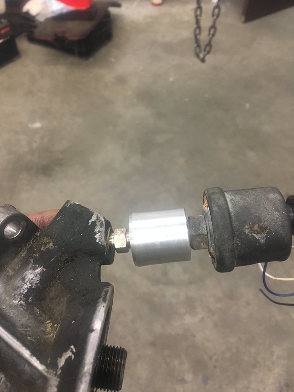
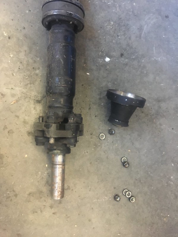
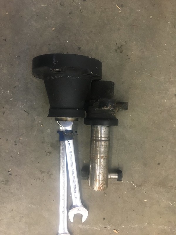
Another project I've been thinking about is a full CV driveshaft. It would utilize BNR32 CVs at each end and a custom slip yoke welded to a BNR32 mid shaft CV flange which are otherwise useless. What you see is an early S13 5 speed driveline that I plan to use. Both parts will be machined, shrink fit, and carefully welded. Will I be able to do it and prevent it from becoming a warped mess? I don't know but it's worth a try.
This will accomplish 2 things:
1) eliminate the unbalanced vibration from the single cardan joint I currently have. You need 2 cardan joints operating at equal angles to cancel the the torsional vibration and maintain a constant output speed. The smaller the operating angle of the single cardan joint, the better but you need a certain operating angle (~0.5-1*) for adequate lubrication to prevent false brinelling so you just can't win. With the constraints of the car, I can't get the cardan angle to be minimized so in my true as difficult as possible manta, I will try something else.
2) Once the CV joints are removed from the shaft (leaving a 3" tube with splined ends, a COMPETENT shop can precision balance the shaft in 2 planes to ISO G1 or G2.5, 20-40 times better than your regular driveline shop.
Should be interesting.
 510 NY 2019 by JordanTr, on Flickr
 510 NY 2019 by JordanTr, on Flickr
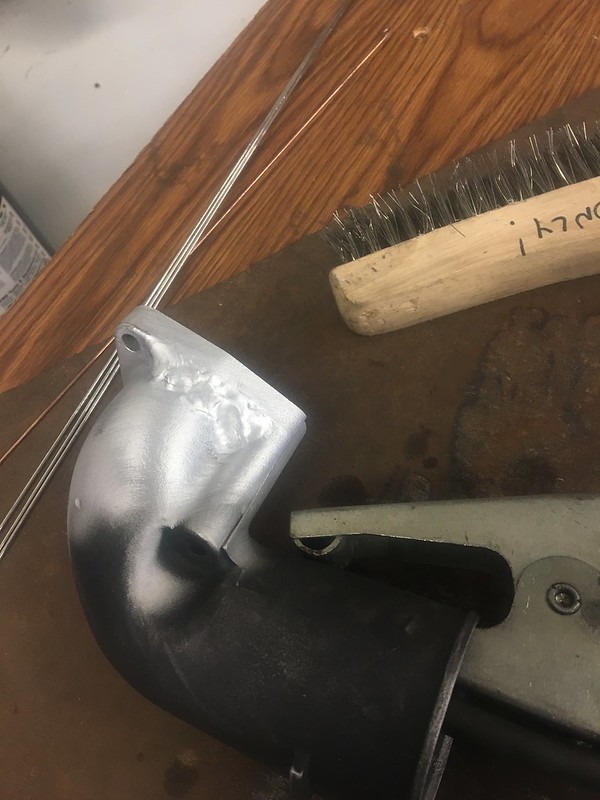
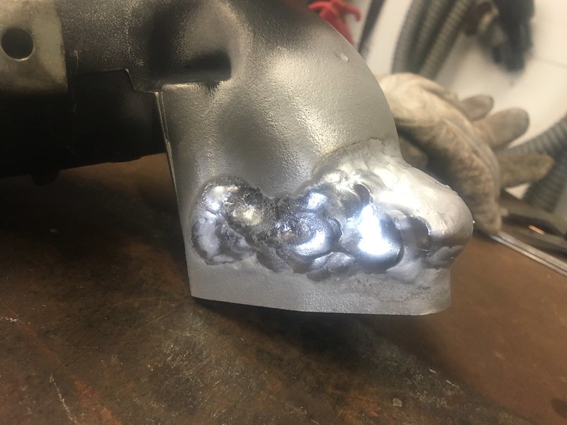
To make room for the compressor elbow on the bottom mounted turbo, I opted to weld buildup the one thin flange and then shave 5/8" off of the mating face. I haven't cleaned it up yet but it is functional and perfectly nests the elbow by the frame rail and inner fender.
 510 NY 2019 by JordanTr, on Flickr
 510 NY 2019 by JordanTr, on Flickr
 510 NY 2019 by JordanTr, on Flickr
 510 NY 2019 by JordanTr, on Flickr
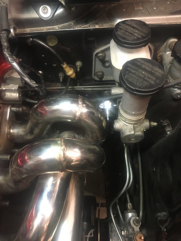
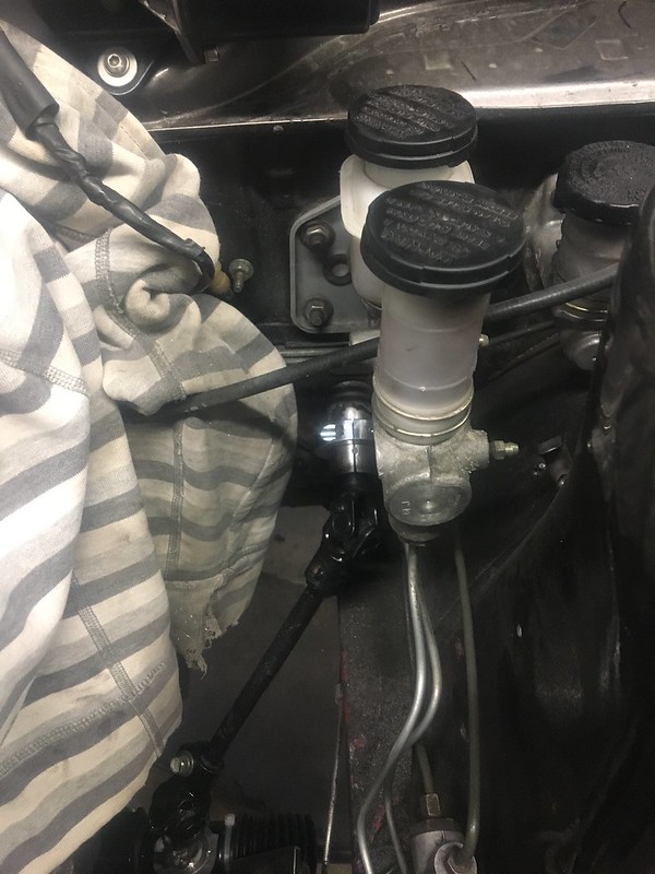
With the new engine placement, suddenly my budget manifold didn't fit quite as well. There was about 1/16" between the manifold and bleeder casting on the master. I wanted enough room for engine movement and to allow a future heat shield. I did 3 things to help gain clearance: shimmed the master over about 1/16" at the firewall on one side to angle it away, BFHed the manifold in the offending zone which gained ~ 1/4", and cut off the blind cast bleeder position (after practicing on a spare!).
After dent
 510 NY 2019 by JordanTr, on Flickr
 510 NY 2019 by JordanTr, on Flickr
 510 NY 2019 by JordanTr, on Flickr
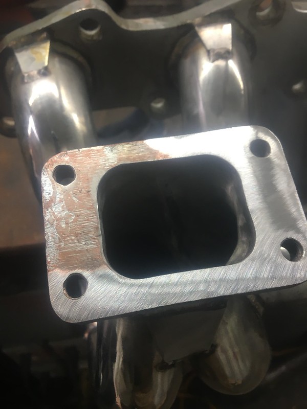
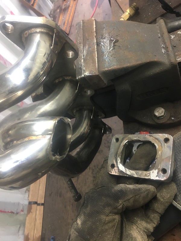
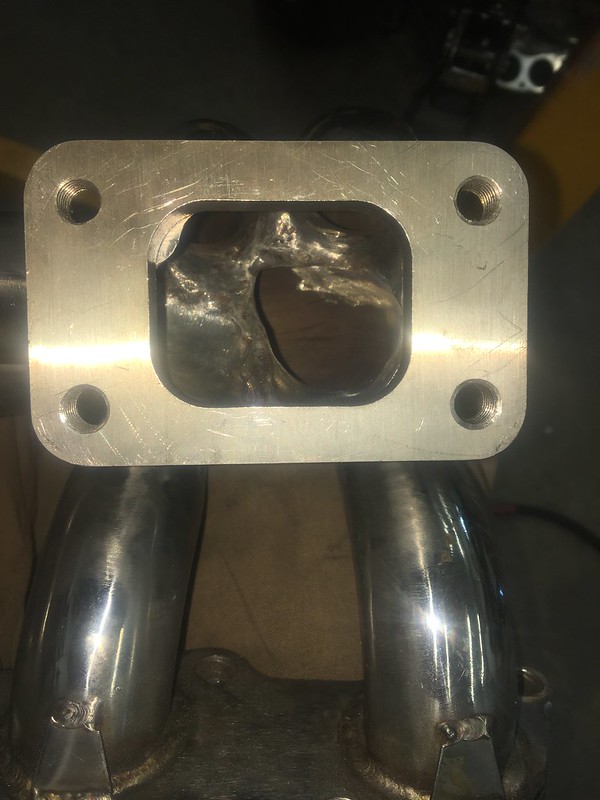
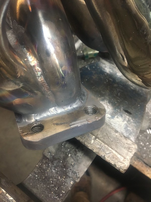
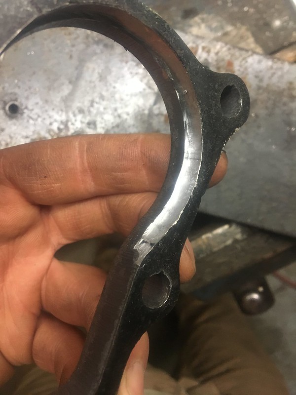
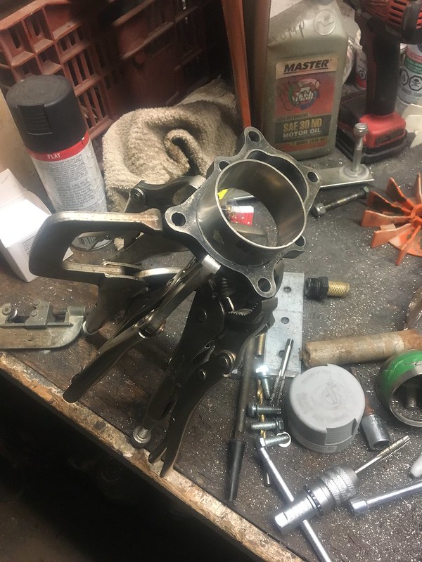
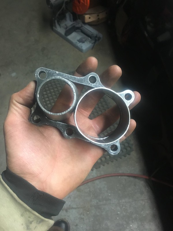
Part of the budget manifold plan was knowing I needed to change from a T2 flange to a T3 flange. The manifold was designed for a SR20 sized turbo so I chopped off the old flange, cleaned and reshaped the tubing, and then welded on the new 304SS T3 flange.
 510 NY 2019 by JordanTr, on Flickr
Trying to jig it up
 510 NY 2019 by JordanTr, on Flickr
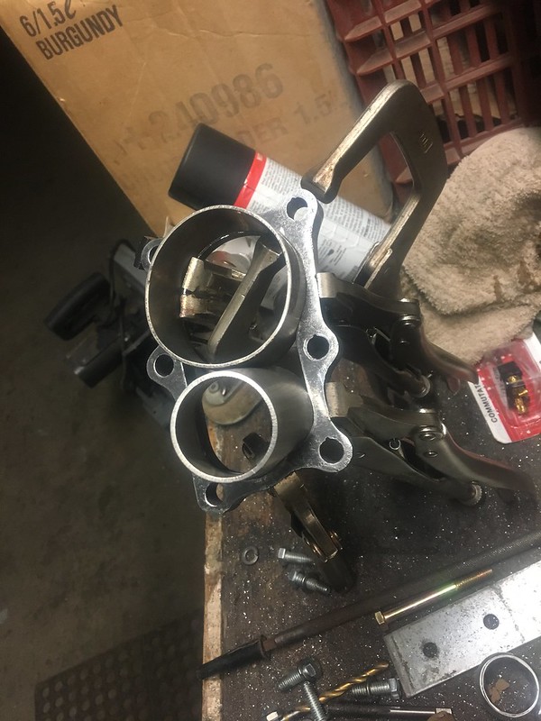
It all fits very nicely except one offending corner.
 510 NY 2019 by JordanTr, on Flickr
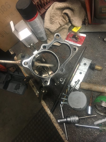
Tacked and confirmed fitment.
 510 NY 2019 by JordanTr, on Flickr
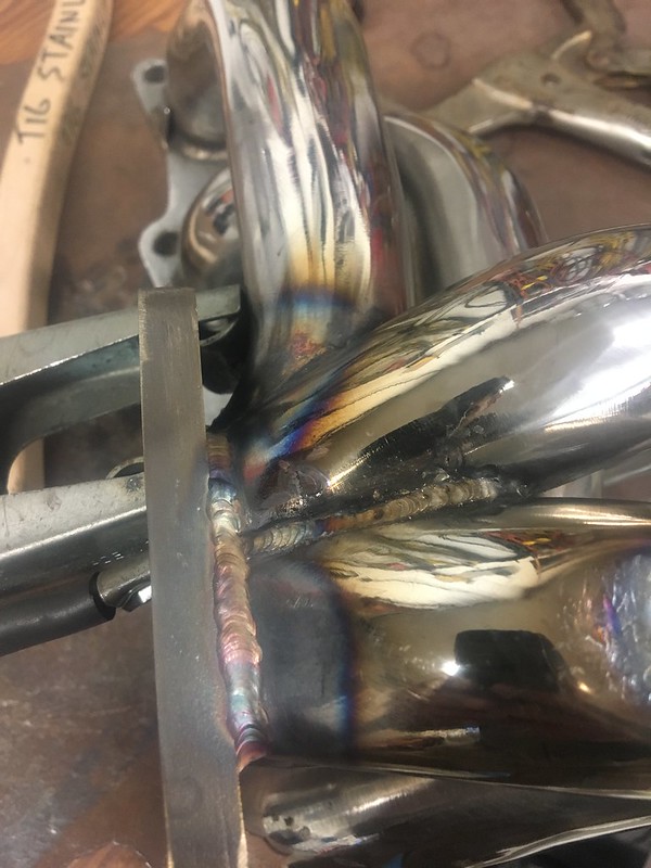
Welded out and WARPED
 510 NY 2019 by JordanTr, on Flickr
 510 NY 2019 by JordanTr, on Flickr
In fact, so warped that I could not even bolt the turbo on since the tapped holes were no longer perpendicular with the flange. Look closely above and you can see it.
After some careful rose budding and BFHing, pops and I got the flange surprisingly true. It'll still get decked but now at least the turbo isn't bolted to a teeter-totter and the bolts work fine.
 510 NY 2019 by JordanTr, on Flickr
With the turbo placement finalized, it was downpipe time!
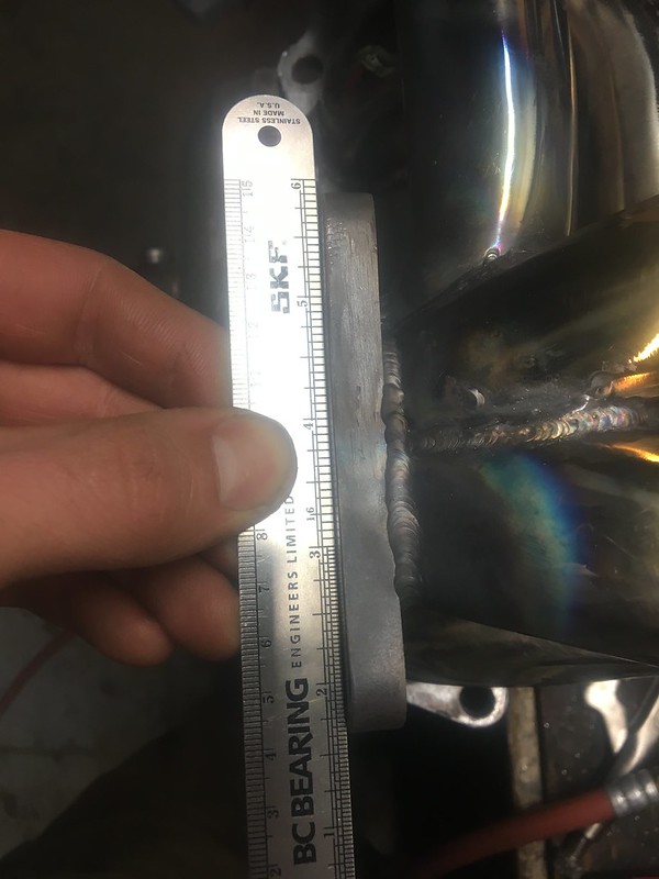
I bought a 12mm flange from eBay UK since I couldn't find anything that appeared reputable closer to home. I did my usual trick of creating a step lip in the flange to nest the pipe into. Once pressed into the flange, the tubing has a very positive fit that's easy to weld. You can also use clamps to force the pipe into all the contours.
 510 NY 2019 by JordanTr, on Flickr
I was able to get 2 1/2" tubing in an almost round condition into the flange although it is tight to the bolts/wrench allowance. This will later be stepped up to 3" as space allows.
 510 NY 2019 by JordanTr, on Flickr
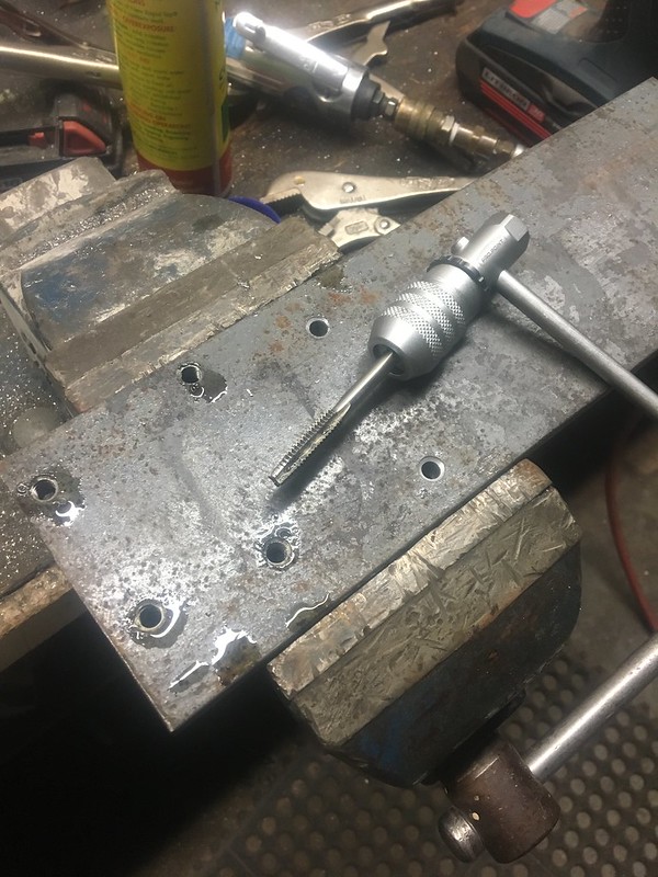
To prevent flange debacle round 2, I drilled/tapped a 1/2" steel plate for fixturing the DP flange to during welding.
 510 NY 2019 by JordanTr, on Flickr
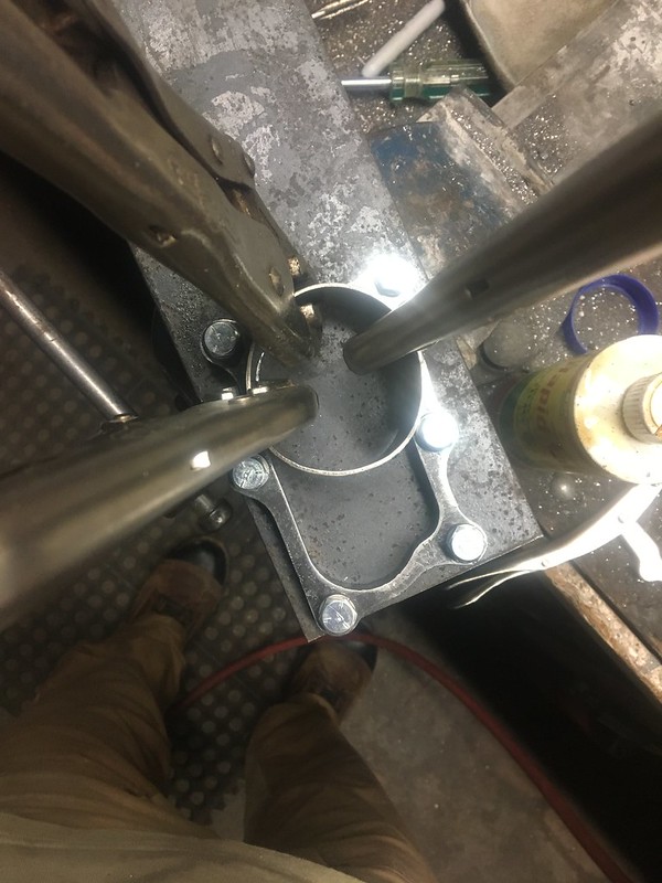
Clamps in action.
 510 NY 2019 by JordanTr, on Flickr
What's better than 3 clamps? 5 clamps.
 510 NY 2019 by JordanTr, on Flickr
I was able to move the engine rearward another 5/16" and I did that by slotting the new engine mount lower plates. It also makes it a little easier to install which is nice. With the engine in its final home, I rebuilt the transmission crossmember. The design is pretty similar to what I had back in 2009 (!!!) and miraculously I was able to find the other half of the square tube I split back in the day. I used a reshaped piece of 6" sched 40 pipe for exhaust clearance on the drivers side.
510 NY 2019 by JordanTr, on FlickrHomemade press
510 NY 2019 by JordanTr, on Flickr510 NY 2019 by JordanTr, on Flickr510 NY 2019 by JordanTr, on Flickr510 NY 2019 by JordanTr, on FlickrAnother project I've been thinking about is a full CV driveshaft. It would utilize BNR32 CVs at each end and a custom slip yoke welded to a BNR32 mid shaft CV flange which are otherwise useless. What you see is an early S13 5 speed driveline that I plan to use. Both parts will be machined, shrink fit, and carefully welded. Will I be able to do it and prevent it from becoming a warped mess? I don't know but it's worth a try.
This will accomplish 2 things:
1) eliminate the unbalanced vibration from the single cardan joint I currently have. You need 2 cardan joints operating at equal angles to cancel the the torsional vibration and maintain a constant output speed. The smaller the operating angle of the single cardan joint, the better but you need a certain operating angle (~0.5-1*) for adequate lubrication to prevent false brinelling so you just can't win. With the constraints of the car, I can't get the cardan angle to be minimized so in my true as difficult as possible manta, I will try something else.
2) Once the CV joints are removed from the shaft (leaving a 3" tube with splined ends, a COMPETENT shop can precision balance the shaft in 2 planes to ISO G1 or G2.5, 20-40 times better than your regular driveline shop.
Should be interesting.
510 NY 2019 by JordanTr, on Flickr510 NY 2019 by JordanTr, on FlickrTo make room for the compressor elbow on the bottom mounted turbo, I opted to weld buildup the one thin flange and then shave 5/8" off of the mating face. I haven't cleaned it up yet but it is functional and perfectly nests the elbow by the frame rail and inner fender.
510 NY 2019 by JordanTr, on Flickr510 NY 2019 by JordanTr, on Flickr510 NY 2019 by JordanTr, on Flickr510 NY 2019 by JordanTr, on FlickrWith the new engine placement, suddenly my budget manifold didn't fit quite as well. There was about 1/16" between the manifold and bleeder casting on the master. I wanted enough room for engine movement and to allow a future heat shield. I did 3 things to help gain clearance: shimmed the master over about 1/16" at the firewall on one side to angle it away, BFHed the manifold in the offending zone which gained ~ 1/4", and cut off the blind cast bleeder position (after practicing on a spare!).
After dent
510 NY 2019 by JordanTr, on Flickr510 NY 2019 by JordanTr, on Flickr510 NY 2019 by JordanTr, on FlickrPart of the budget manifold plan was knowing I needed to change from a T2 flange to a T3 flange. The manifold was designed for a SR20 sized turbo so I chopped off the old flange, cleaned and reshaped the tubing, and then welded on the new 304SS T3 flange.
510 NY 2019 by JordanTr, on FlickrTrying to jig it up
510 NY 2019 by JordanTr, on FlickrIt all fits very nicely except one offending corner.
510 NY 2019 by JordanTr, on FlickrTacked and confirmed fitment.
510 NY 2019 by JordanTr, on FlickrWelded out and WARPED
510 NY 2019 by JordanTr, on Flickr510 NY 2019 by JordanTr, on FlickrIn fact, so warped that I could not even bolt the turbo on since the tapped holes were no longer perpendicular with the flange. Look closely above and you can see it.
After some careful rose budding and BFHing, pops and I got the flange surprisingly true. It'll still get decked but now at least the turbo isn't bolted to a teeter-totter and the bolts work fine.
510 NY 2019 by JordanTr, on FlickrWith the turbo placement finalized, it was downpipe time!
I bought a 12mm flange from eBay UK since I couldn't find anything that appeared reputable closer to home. I did my usual trick of creating a step lip in the flange to nest the pipe into. Once pressed into the flange, the tubing has a very positive fit that's easy to weld. You can also use clamps to force the pipe into all the contours.
510 NY 2019 by JordanTr, on FlickrI was able to get 2 1/2" tubing in an almost round condition into the flange although it is tight to the bolts/wrench allowance. This will later be stepped up to 3" as space allows.
510 NY 2019 by JordanTr, on FlickrTo prevent flange debacle round 2, I drilled/tapped a 1/2" steel plate for fixturing the DP flange to during welding.
510 NY 2019 by JordanTr, on FlickrClamps in action.
510 NY 2019 by JordanTr, on FlickrWhat's better than 3 clamps? 5 clamps.
510 NY 2019 by JordanTr, on Flickr
Last edited by JordanTr on 08 Jan 2019 15:16, edited 1 time in total.
'72 2 door KA project | S14 Silvia RB25DET | S14 RB26DETT (sold) | '90 Audi 90Q20V (sold)
Re: Jordan's '72 2 door KA project
Pressed the wrong button!
 510 NY 2019 by JordanTr, on Flickr
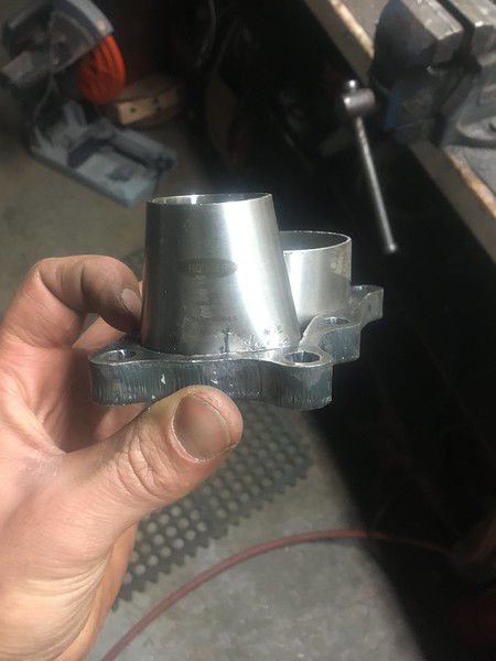
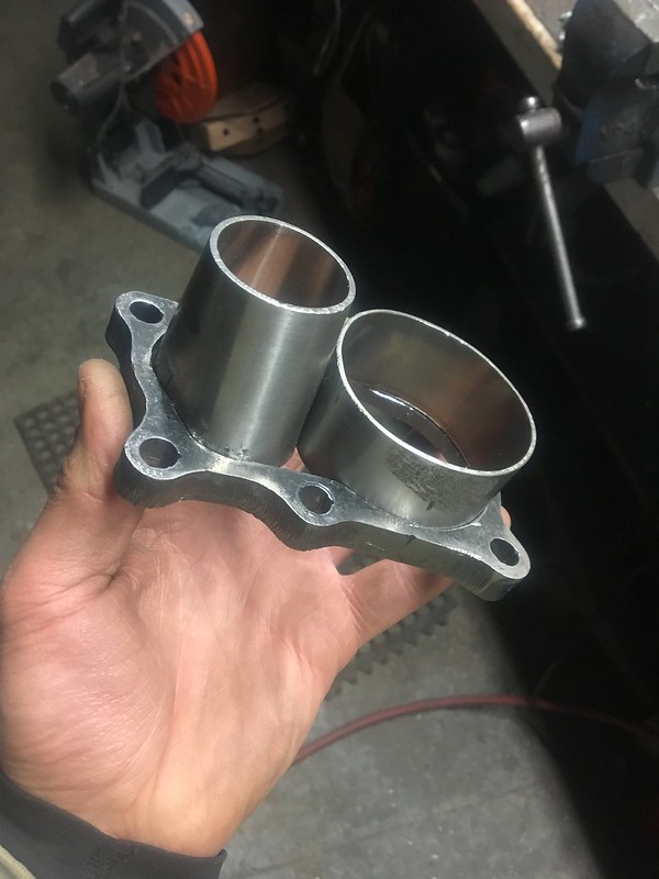
I used a reshaped 2" to 1.5" reducer to get me from the DP flange to 1.5" divorced wastegate tubing. I was amazed how well it actually ended up fitting together. I'll have to seal off the 2 triangles but I am very happy how it came out. With the shoulders and the press fit pipes you need tools to dismantle it as shown.
 510 NY 2019 by JordanTr, on Flickr
 510 NY 2019 by JordanTr, on Flickr
 510 NY 2019 by JordanTr, on Flickr
 510 NY 2019 by JordanTr, on Flickr
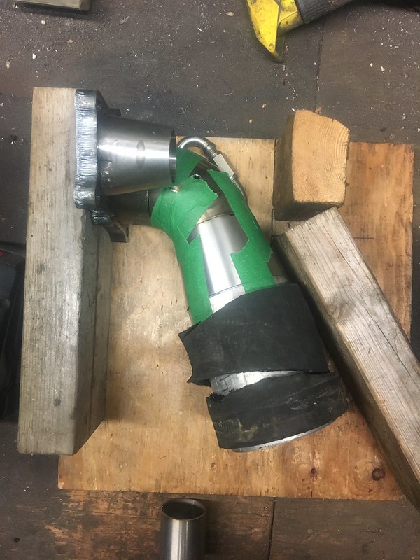
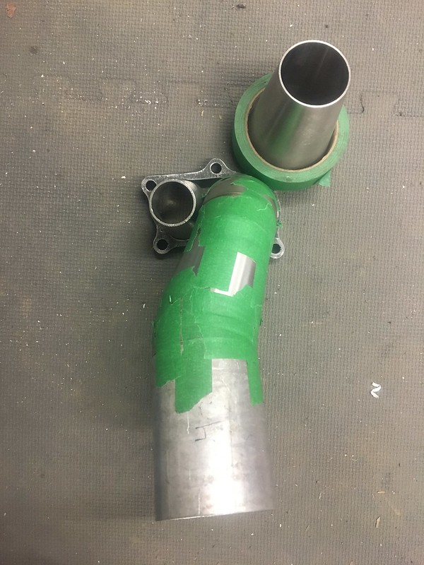
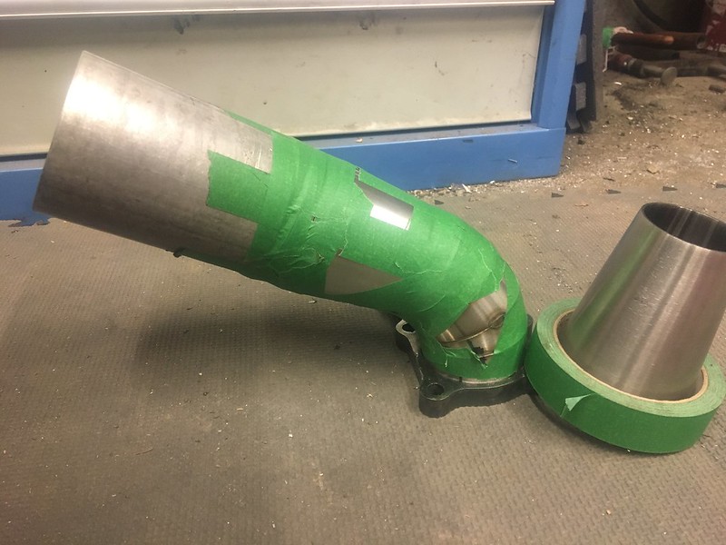
The wooden mockup shows the turbo flange in relation to the firewall. Lots closer now that everything has been moved around in the engine bay. It has a tight pie cut 2.5" bend ~60* and then a step up to 3" with a 3" bellows. Unfortunately I didn't have the bellows yet so imagine it as the rubber part. It is only 4" long so it appear it will fit just right.
 510 NY 2019 by JordanTr, on Flickr
Wastegate piping will be done once the main pipe is all fitted and tacked. The divorced pipe will be cut in mid transition from 2.5 to 3".
 510 NY 2019 by JordanTr, on Flickr
After many trial/error fits, I ended up with this green monster. You can see the 4" aluminum at the end.
 510 NY 2019 by JordanTr, on Flickr
 510 NY 2019 by JordanTr, on Flickr
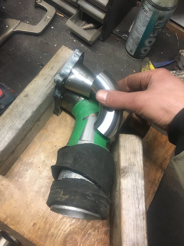
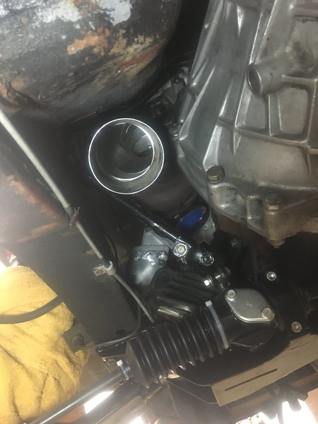
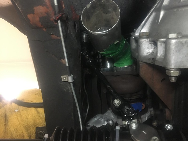
It's hard to get a good perspective on this but the tube is centered in all directions and parellel with the firewall.
 510 NY 2019 by JordanTr, on Flickr
 510 NY 2019 by JordanTr, on Flickr
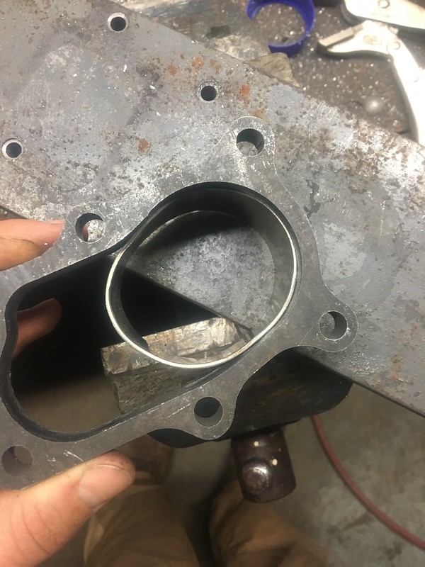
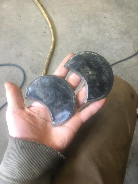
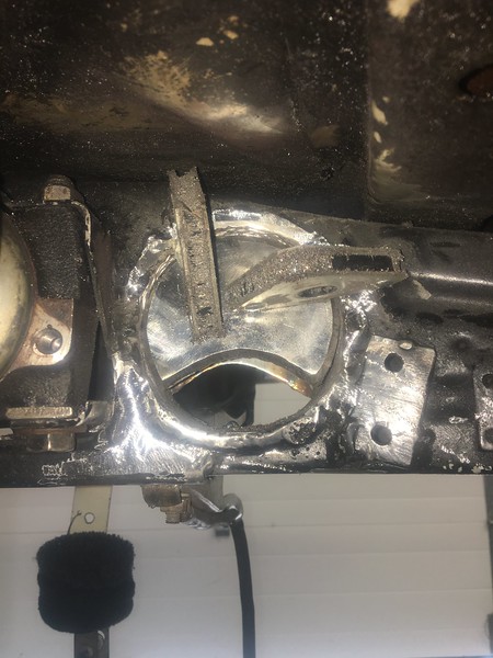
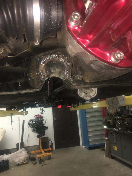
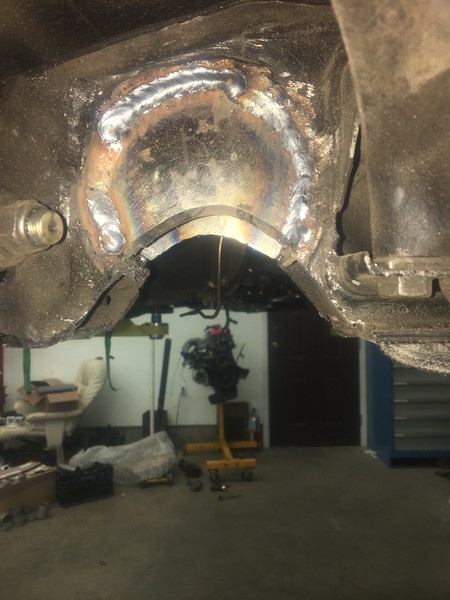
With the now 3" exhaust, I was met with more challenges at the rear of the car. Like a good boy, I had enlarged the rear crossmember hole with encouragement from all here when I had the crossmember out back in the day. This was great for the 2" exhaust but 3" vbands were about 0.15" too big to fit through. Also, don't use rusty pipe the first time around, it'll come back to bite you!
I crunched the numbers for these modifications and it's within a few % of the factory strength once I lap on a patch atop the crossmember once it comes out of the car.
 510 NY 2019 by JordanTr, on Flickr
 510 NY 2019 by JordanTr, on Flickr
 510 NY 2019 by JordanTr, on Flickr
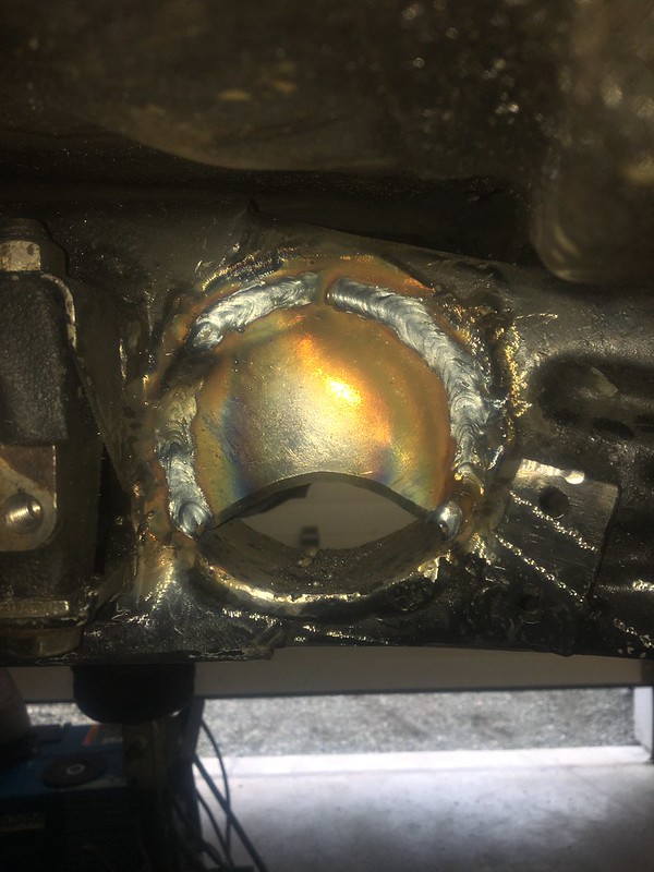
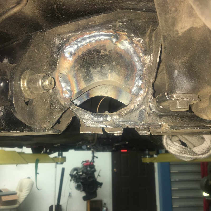
2 pieces of 1/4" plate welded from both sides.
 510 NY 2019 by JordanTr, on Flickr
 510 NY 2019 by JordanTr, on Flickr
 510 NY 2019 by JordanTr, on Flickr
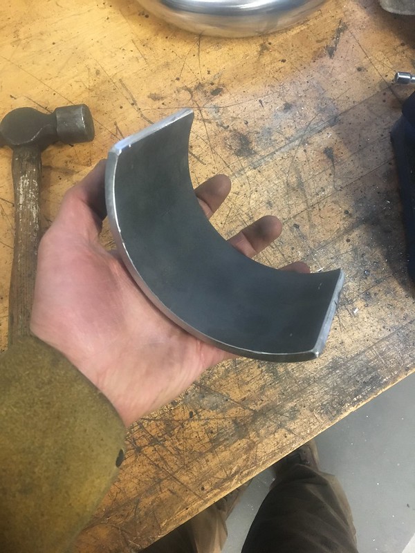
Raw 6" sched 40 pipe (not rusty!)
 510 NY 2019 by JordanTr, on Flickr
Reshaped
 510 NY 2019 by JordanTr, on Flickr
Refitted.
 510 NY 2019 by JordanTr, on Flickr
That's it for now!
510 NY 2019 by JordanTr, on FlickrI used a reshaped 2" to 1.5" reducer to get me from the DP flange to 1.5" divorced wastegate tubing. I was amazed how well it actually ended up fitting together. I'll have to seal off the 2 triangles but I am very happy how it came out. With the shoulders and the press fit pipes you need tools to dismantle it as shown.
510 NY 2019 by JordanTr, on Flickr510 NY 2019 by JordanTr, on Flickr510 NY 2019 by JordanTr, on Flickr510 NY 2019 by JordanTr, on FlickrThe wooden mockup shows the turbo flange in relation to the firewall. Lots closer now that everything has been moved around in the engine bay. It has a tight pie cut 2.5" bend ~60* and then a step up to 3" with a 3" bellows. Unfortunately I didn't have the bellows yet so imagine it as the rubber part. It is only 4" long so it appear it will fit just right.
510 NY 2019 by JordanTr, on FlickrWastegate piping will be done once the main pipe is all fitted and tacked. The divorced pipe will be cut in mid transition from 2.5 to 3".
510 NY 2019 by JordanTr, on FlickrAfter many trial/error fits, I ended up with this green monster. You can see the 4" aluminum at the end.
510 NY 2019 by JordanTr, on Flickr510 NY 2019 by JordanTr, on FlickrIt's hard to get a good perspective on this but the tube is centered in all directions and parellel with the firewall.
510 NY 2019 by JordanTr, on Flickr510 NY 2019 by JordanTr, on FlickrWith the now 3" exhaust, I was met with more challenges at the rear of the car. Like a good boy, I had enlarged the rear crossmember hole with encouragement from all here when I had the crossmember out back in the day. This was great for the 2" exhaust but 3" vbands were about 0.15" too big to fit through. Also, don't use rusty pipe the first time around, it'll come back to bite you!
I crunched the numbers for these modifications and it's within a few % of the factory strength once I lap on a patch atop the crossmember once it comes out of the car.
510 NY 2019 by JordanTr, on Flickr510 NY 2019 by JordanTr, on Flickr510 NY 2019 by JordanTr, on Flickr2 pieces of 1/4" plate welded from both sides.
510 NY 2019 by JordanTr, on Flickr510 NY 2019 by JordanTr, on Flickr510 NY 2019 by JordanTr, on FlickrRaw 6" sched 40 pipe (not rusty!)
510 NY 2019 by JordanTr, on FlickrReshaped
510 NY 2019 by JordanTr, on FlickrRefitted.
510 NY 2019 by JordanTr, on FlickrThat's it for now!
'72 2 door KA project | S14 Silvia RB25DET | S14 RB26DETT (sold) | '90 Audi 90Q20V (sold)
Re: Jordan's '72 2 door KA project
love it - fearless by numbers
Re: Jordan's '72 2 door KA project
As much as I’d like to be a brave pioneer, this has been done on a 510 in Australia. Jeff’s white coupe (SX-510 on here) was modified for a short nose r200 and the crossmember was arched for exhaust as well. There are pictures somewhere on Ozdat. I believe there are videos of his 510 coupe running pretty quick 1/4 miles.
Aside from the cleaner exhaust routing, I don’t know how I would have removed and replaced the current tube in the xmember without making a colossal mess.
'72 2 door KA project | S14 Silvia RB25DET | S14 RB26DETT (sold) | '90 Audi 90Q20V (sold)