So next up is the wiring. This is the one area that I was feeling the least comfortable with. First off, I want to give special thanks to Jeff (Icehouse on Ratsun) for putting together a fantastic, easy to understand wiring diagram for installing a VG into a 510.
I have been spending many hours studying the VG FSM and the 510 wiring diagrams from Paolo. After many hours going through them, I finally had an idea of what everything was and what went to where.
So I set up a large table in my basement and laid out the VG ECCS harness and started to identify and label all of the connections. I tore into the 510 engine compartment harness, completely unwrapped it, and got rid of stuff I didn't need and extended and rerouted the wires I needed moved. It was nice to have this setup inside as it is friggin freezing out in the garage.
Last week, it got warmer for a few days, so I took the ECCS harness out to the garage and decided how I would route everything and where I would bring the harness through the firewall and into the car. Then I figured out where I wanted to mount the ECU. I had seen enough rats next wiring jobs to know that I wanted mine to be neat and out of the way of clumsy passenger feet.
My good buddy Lou sent me a link to a website in Australia that does custom ECU wiring and they made a really sweet panel that mounted up under the glove box area.
http://www.plmsdevelopments.com/510_mtg_plate.htm
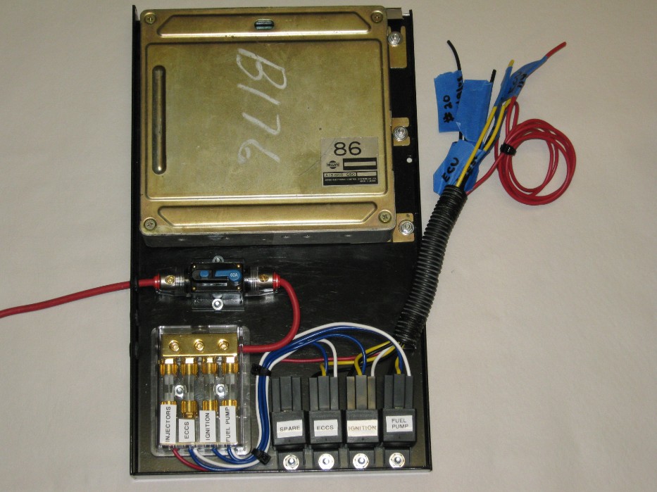
I decided I wanted to mount the ECU in a similar fashion. While I had the warmer weather, I ran all of the wires from the trunk area to the front of the car under the dash. Then I moved onto building my ECU panel. This above panel was my inspiration.
I found a panel (an old computer keyboard tray from a metal desk) and went to work.
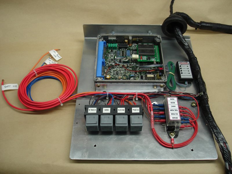
Below is the result of too many hours spent on this.
I finalized this ECU panel today. All the connections to the new ECCS fuse box and
relays have been hooked up and tied in.
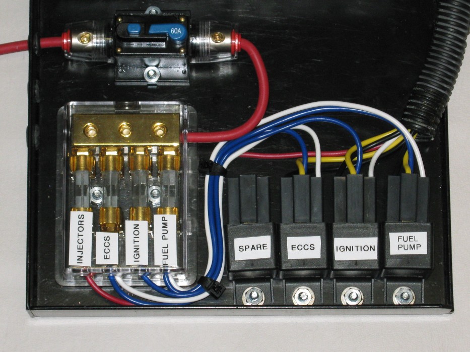
I am using a trunk mounted battery. I will be using a Ford type Starter Solenoid mounted in the trunk, next to the battery, so the main power cable to the starter will only be hot while cranking. You can see the red 8 gauge wire coming in on the left of the ECU panel, that feeds 12v from the trunk mounted starter solenoid. I will have an inline fuse in the trunk to protect the 8 gauge wire. The wire will come through the interior, under the back seat and follow the trans tunnel to under the dash. It then passes though a grommet on the side of the ECU panel and feeds a 60 amp resettable circuit breaker. From there it goes to the fuse box which is also a distribution block. It has 2 more outputs on it. One will feed another 8 gauge which goes to the alternator. The other one will feed the fans, headlights and horn. As you can see, I installed a spare relay in case one goes bad on me while I am away from home. This way, I can just unplug the relay harness and plug it onto the spare.
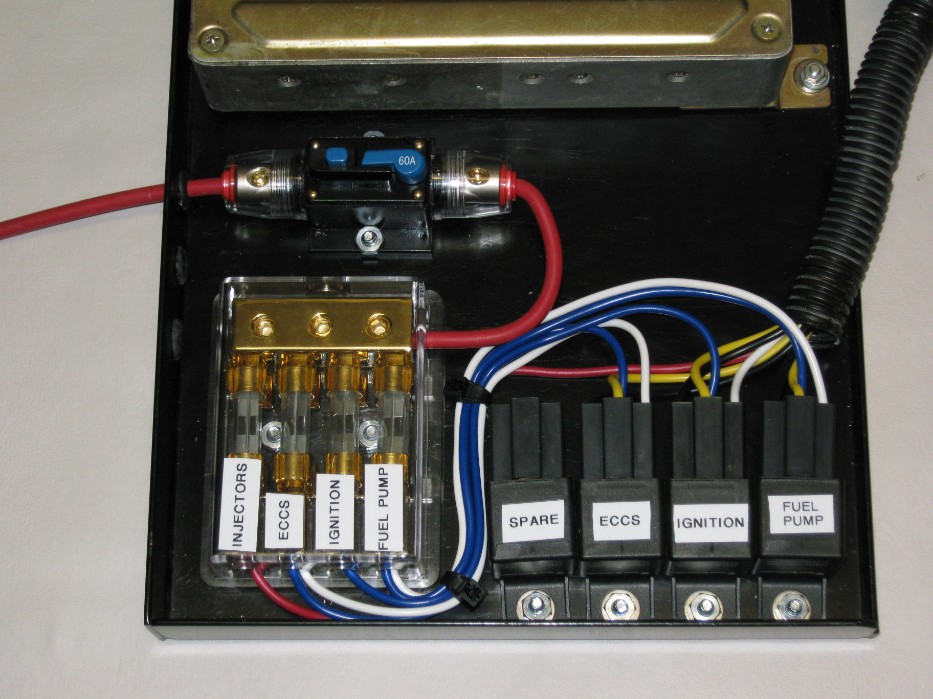
The 3 connectors from the ECU wiring harness plug in on the right side of the ECU
by those other wires. There are only 8 wires there. I labeled them, 5 of them hook
into the ECU wiring. I will tie them in to the proper wires which I have marked on the
ECU harness.
So it is pretty easy at this point. I am considering using bullet connectors for those
8 wires so I will be able to disconnect them easily if I ever need to service this setup.
That will make the wiring to this panel fully separate except for the 8 gauge wires
which can be disconnected easily. I made sure to leave alot of extra wire so I can have
a service loop when the panel is in the down position.
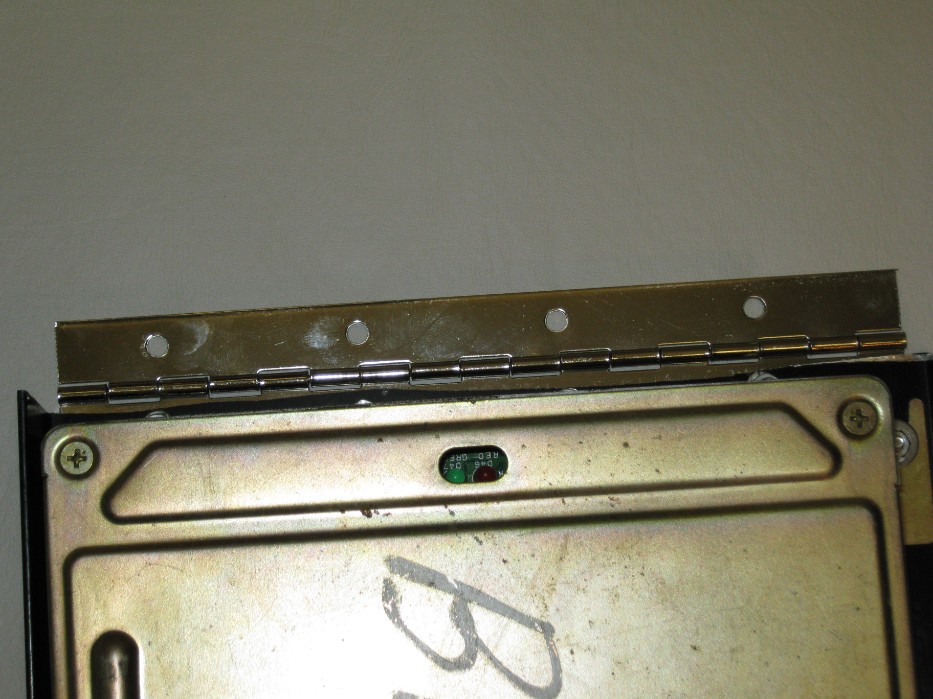
I mounted a piano hinge on the back of the panel that will mount to the firewall. This will allow the panel to swing down for easy access.
The panel has a nice deep lip on the front so it will all be concealed when in place under the glove box. The front edge of the lip lines up with the edge of the glove box where it meets the dash.
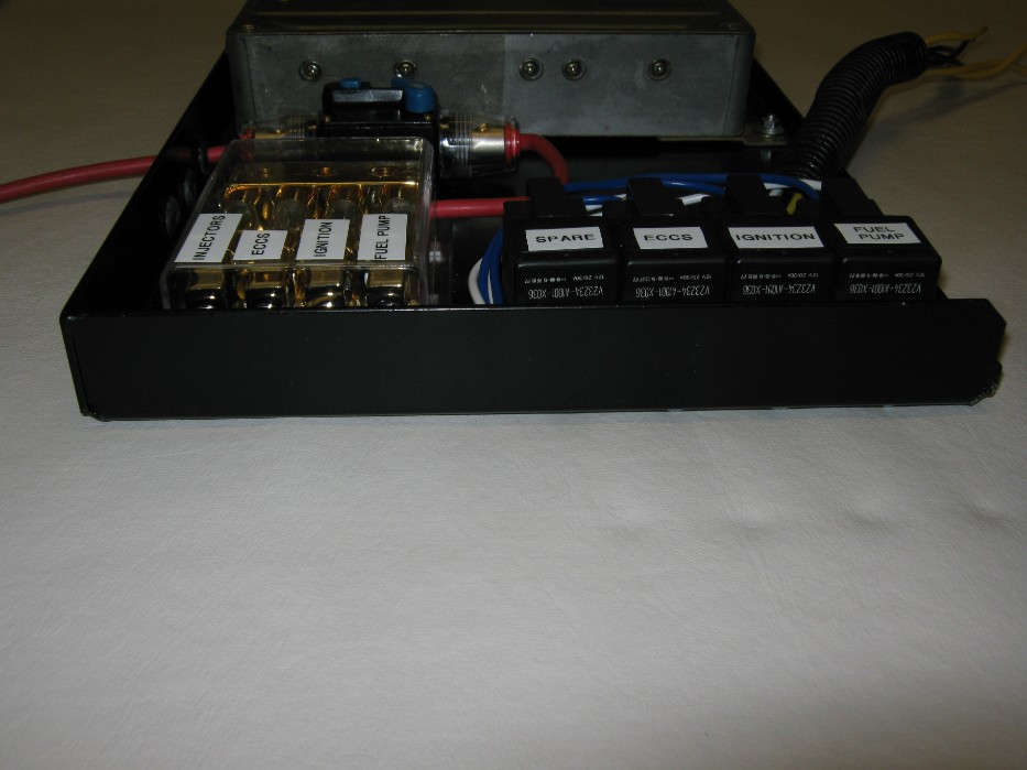
I still need to figure out how I will latch it up so it can be easily released for access. If you have any ideas for a latch, let me know.
I put many hours into making this panel. Time I could have used on other things. Oh well, it is done now and I am very happy with the way it turned out.
Next up, I will be temporarily hooking it all up in the car and testing all of the circuits to make sure everything is working properly. Once that is done, I will wrap the harnesses and finally install them permanently and hopefully be trying to fire it up really soon.
More to come soon.


)